hi folks,
well ive got the above amp which i have repaired a few times. however i'ts now popped one of the o/p trannys, they are craftily labelled f15n/f15p. obviously these are mf's own codes, a habit they are fond of so they can rip you off when you need replacements.
there's a total of 4 per channel.
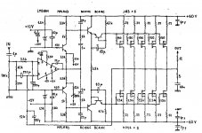
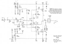
i've no idea if they are mosfet or bipolar. circuit consists of (input to output ) - 5534 and 5532 , then x2 of each mps a92/a42 (which ive changed a few times), followed by 2sd649/669 pair then the big TO3 f15n/f15p pairs. there is a bias pot too.
amp always sounded good but is terribly designed from an engineering point. originally had x4 50V 10000uf smoothing caps, running at , u guessed it, over 50v (53ish). changed them for 63v while ago.
i actually wrote to MF 1st time those caps dried out, pointing out the problem. Engineering director wrote back claiming the caps were rated at +10% so 55v . pah! the cheek of it.
also the mpsa92/42's literally cook, along with two 1/4 1k0 metal film resistors which should def have been 1/2 watt.
anyway, im flat broke at the minute and need to revive this beast.
if anyone can help with any info i'd be extremely grateful.
many thanks
raymond
well ive got the above amp which i have repaired a few times. however i'ts now popped one of the o/p trannys, they are craftily labelled f15n/f15p. obviously these are mf's own codes, a habit they are fond of so they can rip you off when you need replacements.
there's a total of 4 per channel.
i've no idea if they are mosfet or bipolar. circuit consists of (input to output ) - 5534 and 5532 , then x2 of each mps a92/a42 (which ive changed a few times), followed by 2sd649/669 pair then the big TO3 f15n/f15p pairs. there is a bias pot too.
amp always sounded good but is terribly designed from an engineering point. originally had x4 50V 10000uf smoothing caps, running at , u guessed it, over 50v (53ish). changed them for 63v while ago.
i actually wrote to MF 1st time those caps dried out, pointing out the problem. Engineering director wrote back claiming the caps were rated at +10% so 55v . pah! the cheek of it.
also the mpsa92/42's literally cook, along with two 1/4 1k0 metal film resistors which should def have been 1/2 watt.
anyway, im flat broke at the minute and need to revive this beast.
if anyone can help with any info i'd be extremely grateful.
many thanks
raymond
post a picture of amp inside , so we can compare it with some schematics we have ......
("we" - any of us )
)
("we" - any of us
)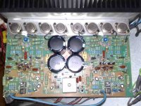
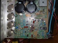
send few full res pics to >choky@neobee.net<
try at least to measure one output transistor - on good channel - is it bjt , with simple diode test on DVM
try at least to measure one output transistor - on good channel - is it bjt , with simple diode test on DVM
pics
hi , i will send you some full res images when i get home later, thanks for the interest greatly appreciated.
will measure one tonight , one channel definately ok .
hi , i will send you some full res images when i get home later, thanks for the interest greatly appreciated.
will measure one tonight , one channel definately ok .
Re: reallly!?
look at this :
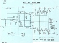
A370
looks pretty much similar
I'll look more - later
poynton said:Remarked Exicon Lateral Mosfets
Andy
raymondo said:any numbers andy? thanks a lot
look at this :
A370
looks pretty much similar
I'll look more - later
Attachments
Re: Re: reallly!?
Cleaned up your signature line I see...😀
Zen Mod said:
look at this :
Cleaned up your signature line I see...😀
sig
yup;
I received ultimatum note from mod team :
"either shorten sig line , or we are going to leave DiyA "
so - in interest of community - I shorted sig .

MJL21193 said:
Cleaned up your signature line I see...😀
yup;
I received ultimatum note from mod team :
"either shorten sig line , or we are going to leave DiyA "
so - in interest of community - I shorted sig .
Raymondo
I have most versions of the Musical Fidelity amps other than yours.
From the photo your amp seems to have a circuit similar to the p270 but running at much lower bias ( the heat sink is small compared to the P270). Your amp seems to use the ic input stage and the circuit may be similar to that in post 14. However I would guess that the stage just after the ic in that circuit is missed out as it was in most of the P270's.
You are correct about the resistor that reduces the input voltage to the front end. It is far to small a wattage value. I changed them to 10watt resistors. The best solution is to change to a pass transistor arrangement that reduces the voltage. This system is used in the later A370.s. This circuit for the pass transistor is shown in one the MF threads - although at the moment I do not remember which one.
All the other MF amps use mosfet output devices. Each output device will have its own source resistor of about 0.3 to 1.0 ohms. If they are 0.3 ohms then the devices will probably all need to be matched however if the resistors are 1.0 ohm than they probably do not need to be matched.
If you can provide some more information on the actual circuit in your amp or if you can test a working output device and tell us if is a mosfet or a transistor we can probably help further.
Don
info
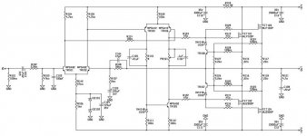
hey thanks for all that. now the cct that looks the closest is the a1000 on the japanese site. that amp uses a1000n/p though, and i have a feeling these are mosfets in mine . but the other components look almost identical (esp those non-polar brown capacitors).
suppose my could be a hybrid of the two. looks like they made many flavours of the same basic amp with tweaks and sometimes mosfets , sometimes bipolar.
andy are u sure they are mosfets?
thanks a lot guys. wasted whole day at work on this forum forgot how good it was!
- Home
- Amplifiers
- Solid State
- Musical Fidelity e300 power amp trannys help :(