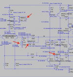
This is looking better. I've added a parallel 27pF to the filter cap on the first stage. I've also switched the models of the zener and the 92/42 to the Fairchild model which I believe fits closer to the measurements.
I've been going over and measuring every point on the system using the SDS1104 in DC coupling - at 50MS/s far more accurate than my crappy multimeter. I've now marked these on the schematic as "M:".
I've updated the models in the .asc file so you can add to your library if you don't have it.
ONE THING - as the BUZ model is a 200W variant, it keeps 2.5A through the fets and that causes the problem with bias for TR106. In short the measurements show that the model is constantly putting 4V on the gate bias of the P-channels rather than the ~1.5V. Hence the mess.
Attachments
I've also been interested in nyquest plots - aß < 1 (unity) means that the resonance would fall away, >1 and it will build thus be unstable.
The image shows the nyquist plot and it seem to indicate that the amp would be stable, although with some HF noise.

The image shows the nyquist plot and it seem to indicate that the amp would be stable, although with some HF noise.
Looks like I'm going to have to recap the MM pre-section too. I've not bothered previously but the resistors on the MM power rails seem hot/discoloured PCB above the traces which points at the old caps there also being almost dead and no capacitance. With the new power rails fixed it seems like you simply need to rip and replace given it simply has a domino effect. I thought about simply disconnecting the MM pre but I'l like it 'complete' in that it's all working and done.
It also gives me a chance to replace R110 which sit between two film caps, this has the main current flowing through it for the driver section. The resistor looks discoloured/darkened so I will replace this by an over rated 2W Vishay-Dale metal film.
Although I'm tempted to go through the signal path and upgrade I think I will stop with the addition of the compensation caps/resistor etc. At least until the changes have had time to bed in and I can listen. Although I have an itch to replace the pre ceramics with WIMAs.. you have to draw the line 😀
Being a little OCD in the approach - I've drawn out the schematic for the preamp power supply and the MM section where I'll be replacing the caps.
Quelle surprise the MM signal goes through a 10uF electrolytic and then the amplified signal goes back through another 10uF electrolytic before it goes to the source selector and before it (originally) hit yet another 10uF electrolytic. So I think MF used the 'lytics to smooth over the tone/detail given they've used film caps etc elsewhere.


You'll note the discolouration of R201 and R202 indicating that the caps are not holding charge thus pulling high current..
The preamp+mm power supply is a simple configuration before the long trip over the PCB to the preamp itself before a 100uF is used to decouple the power rails of the MC33079P.
For this reason I think some reasoning for some changes:
a) some Nichicon MUSE ES bypassed with a film cap would be a better in-signal-path 10uF cap for the MM stage (ie C14 and C23).
b) the MC33079P could do with a second small bypass to reduce PS noise at the chip pin. Although I have replaced the Jamison with a low ESR Panasonic a small cap here to filter off HF to ground could be good. Also a direct ground wire to the centre star wild also be good, currently any ground currents have to navigate a load of trace and over a topboard link across the signal traces
c) the PS reserve caps are 50V 100uF providing local main rail reserve and then 1000uF 16V (C203/204) on the pre-mm power rails. So I think these can be replaced - I'm tempted by some Al organics and/or although either Panasonic or CDE would do well here. Same with 201 on the rail.
d) The PS is fed by two very thin elevated resistors (not on the schematic) but they could be uprated in wattage as they seem darker colour.
I don't think the MM stage design warrants a massive change in the remaining components but R30 & R130 could be upgraded with higher tolerance/lower noise as this seems to be cartridge loading, then R31/32/R131/R132 are pre-op amp signal path resistors. I will leave them but a suggestion for anyone interested. The 10uF caps could be replaced with a MKP 10uF bypassed by a small FKP but they would been fitting under the PCB. R46/R146 could also be improved as they're sat in the signal path from the output of the MC33079P.
Lastly - it appears my A220 PCB was broken from the factory, as there's bodge for connecting the volume pot as there' no PCB pad!

Being a little slow but will spec out he parts and order today and that will complete the repair with a few rational improvements.
Quelle surprise the MM signal goes through a 10uF electrolytic and then the amplified signal goes back through another 10uF electrolytic before it goes to the source selector and before it (originally) hit yet another 10uF electrolytic. So I think MF used the 'lytics to smooth over the tone/detail given they've used film caps etc elsewhere.
You'll note the discolouration of R201 and R202 indicating that the caps are not holding charge thus pulling high current..
The preamp+mm power supply is a simple configuration before the long trip over the PCB to the preamp itself before a 100uF is used to decouple the power rails of the MC33079P.
For this reason I think some reasoning for some changes:
a) some Nichicon MUSE ES bypassed with a film cap would be a better in-signal-path 10uF cap for the MM stage (ie C14 and C23).
b) the MC33079P could do with a second small bypass to reduce PS noise at the chip pin. Although I have replaced the Jamison with a low ESR Panasonic a small cap here to filter off HF to ground could be good. Also a direct ground wire to the centre star wild also be good, currently any ground currents have to navigate a load of trace and over a topboard link across the signal traces
c) the PS reserve caps are 50V 100uF providing local main rail reserve and then 1000uF 16V (C203/204) on the pre-mm power rails. So I think these can be replaced - I'm tempted by some Al organics and/or although either Panasonic or CDE would do well here. Same with 201 on the rail.
d) The PS is fed by two very thin elevated resistors (not on the schematic) but they could be uprated in wattage as they seem darker colour.
I don't think the MM stage design warrants a massive change in the remaining components but R30 & R130 could be upgraded with higher tolerance/lower noise as this seems to be cartridge loading, then R31/32/R131/R132 are pre-op amp signal path resistors. I will leave them but a suggestion for anyone interested. The 10uF caps could be replaced with a MKP 10uF bypassed by a small FKP but they would been fitting under the PCB. R46/R146 could also be improved as they're sat in the signal path from the output of the MC33079P.
Lastly - it appears my A220 PCB was broken from the factory, as there's bodge for connecting the volume pot as there' no PCB pad!
Being a little slow but will spec out he parts and order today and that will complete the repair with a few rational improvements.
Noted I've not documented the bias of the setup. It appears that the left channel is running, at low volume, at 180mV/0.22 = 818mA across the 0.22 output resistors. It's at this point I noted that the right side showed this at full volume (blue left, yellow right channel).

So I checked my bourns 1K pots by taking the voltage on either side. 1.50Vdc on both and it appears -1.44Vdc (L) and -1.55Vdc (R) on the other side so the bias is out on the right side. I've never noted that as I've not played at full volume but it's something I can correct easily 😀
I'll double check the bias for both sides once I'm done.
Noted I've not documented the bias of the setup. So I've used three meters here - scope set to 20MHz limit the CH1&2 then math- and use the mean after the number of samples has stabilised it. This is showing about 1-1.4mV across the 0.22uF resistor thus about 4.5-6.3mA with zero volume. At 2VPP output across the 8ohm load, with a 6KHz signal, that's showing about 20mV/0.22 = 90mA. At FV that's even higher. Unfortunately the scope doesn't have a DC filter only on the probes and can't use 4 channels to take the AC and DC coupling then subtract the AC-DC) to give the final DC only offset in realtime for each sample..
I've reversed engineered the pre/MM power supply, the MM and the preamp stages. Sorry for being slow but I want to be sure I understand the components and the design and not simply replace by firing the parts cannon at it. There's a correction on the MM schematic at the input.


First the regulated PS and the MM stage.
The caps for the PS can be replaced but you can see the resistors on the left have some heat damage due to the high current flow from the old Jamicon caps failing.
Measuring the voltage they are close to the rating so I will update the caps from 16V to 25V and 105degC, with high mA and low ESR. The resistors I will update with 2W pieces to reduce noise this also should reduce noise (R203/R204/R201/R203). I know the later models have a larger resistor in these positions - wire wound may also be better here. I will increase capacitance of the rail caps C201/202.
The MM stage 'lytics also need replacing, however on reverse engineering there's four that are sat on the signal path. They are 10uF so I think the best option here is to use Nichicon MUSE ES and bypass with a FKP/MKP. The two remaining filter caps on the front of the MM stage I'll use Panasonic caps.
If I wanted to improve the sound then I could focus on R30 R130 etc at the front of the MM stage but I will leave that to another stage.
Next the Pre-amp stage used by all stages and MM.

(note this is flipped as if viewing from the underside of the PCB.
I've already replaced the power decoupling caps with Panasonic low ESR caps, however I now need to replace the input coupling caps situated miles away (3") on the signal path C25/C125. At 10uF I think I'll use a 105degC lytic with a FKP/MKP in bypass. There won't be enough space for a 10uF MKP.
I'm contemplating replacing the resistors with higher wattage to reduce the noise, parallel resistors would reduce it a bit but probably not worth the investment given the design.
The MC33079 is not the fastest (7V/uS 16MHz bandwidth) or lowest noise opamp but I want to keep the character/tone but improve clarity.
I think the noise would be be better tackled by addressing the road trip that the signal has to make:

One major modification would be to create a relay draughter card to perform the tape/preout monitor switching. The daughter card can be situated on top/close to the source selector with the monitor switch now being used to switch on/off the relay. The signal can then be send via a shielded coax across to the MC33079 input.
The second major mod would be to use a shielded coax to the volume pot (changing it for a attenuator would be superb but there's some physical logistics to get that in).
First the regulated PS and the MM stage.
The caps for the PS can be replaced but you can see the resistors on the left have some heat damage due to the high current flow from the old Jamicon caps failing.
Measuring the voltage they are close to the rating so I will update the caps from 16V to 25V and 105degC, with high mA and low ESR. The resistors I will update with 2W pieces to reduce noise this also should reduce noise (R203/R204/R201/R203). I know the later models have a larger resistor in these positions - wire wound may also be better here. I will increase capacitance of the rail caps C201/202.
The MM stage 'lytics also need replacing, however on reverse engineering there's four that are sat on the signal path. They are 10uF so I think the best option here is to use Nichicon MUSE ES and bypass with a FKP/MKP. The two remaining filter caps on the front of the MM stage I'll use Panasonic caps.
If I wanted to improve the sound then I could focus on R30 R130 etc at the front of the MM stage but I will leave that to another stage.
Next the Pre-amp stage used by all stages and MM.
(note this is flipped as if viewing from the underside of the PCB.
I've already replaced the power decoupling caps with Panasonic low ESR caps, however I now need to replace the input coupling caps situated miles away (3") on the signal path C25/C125. At 10uF I think I'll use a 105degC lytic with a FKP/MKP in bypass. There won't be enough space for a 10uF MKP.
I'm contemplating replacing the resistors with higher wattage to reduce the noise, parallel resistors would reduce it a bit but probably not worth the investment given the design.
The MC33079 is not the fastest (7V/uS 16MHz bandwidth) or lowest noise opamp but I want to keep the character/tone but improve clarity.
I think the noise would be be better tackled by addressing the road trip that the signal has to make:
One major modification would be to create a relay draughter card to perform the tape/preout monitor switching. The daughter card can be situated on top/close to the source selector with the monitor switch now being used to switch on/off the relay. The signal can then be send via a shielded coax across to the MC33079 input.
The second major mod would be to use a shielded coax to the volume pot (changing it for a attenuator would be superb but there's some physical logistics to get that in).
Parts ordered..
For the reg psu i have decided to try alu polymer caps for the rails. Bit the bullet with 10uF coupling caps as MKP10 which will be large.
Replacement resistors are CPF.
For the reg psu i have decided to try alu polymer caps for the rails. Bit the bullet with 10uF coupling caps as MKP10 which will be large.
Replacement resistors are CPF.
I should have put this in the previous post to stop spammage but I was short of time . I'm just highlighting one channel here but the opposite channel component needs the changes too.
Frequency compensation
Power stage fixes
Preamp fixes
* 24 y/o C25/C125 Jamicon 'lytic signal path replaced by WIMA MKP4 10uF 100V I may bypass with FKP1 caps.
I resisted the urge to replace all the signal resistors with larger ones at this time.
Preamp/MM regulated power supply
The AZA caps take a hit for frequency derating for low frequency up to 0.15 but given their ripple is in the order of 4000mA this isn't an issue with the MC33079 taking ~12mA from the supply rails. I'll admit I wanted to see how these Al organics compare and I hope that the low ESR isn't going to be too much of a problem. I'm expecting iron solid supply rails!
MM stage
Last but not lest the Schaffner FN9262-6-06 IEC power line filter. For now I've given the benefit of the doubt to the diodes as they test ok..
The only other caps are Panasonics for the 24y/o Myriad MC100 CD player power board (2x1000uF+4700uF and a 100uF).
That will do for now. It should solve the power problem, all the Jamicons will have been replaced along with any damage they've been causing.
Frequency compensation
- TDK 27pF C0G 5% 100V caps for Cadded1 on the LTP around C124 and Cadded4 around the TR106
- TDK 10pF C0G 0.5pF 100V caps for C104
- CPF3 10K 1% 3W for Radded3 - way over the top wattage but if this doesn't work I can use it for the tube amps.
Power stage fixes
- 24y/o C103 100uF Jamicon 'lytic - this will be bypassed but I ordered Panasonic FR 25V as a slot in replacement should I back out the freq compensation.
- C101 0.22uF MPP -> WIMA 1uF MKP10 5% I have already that's burnt in.
- discoloured R106 1K is being upgraded to CPF3 3W 0.1%
- discoloured R110 6.8K is being upgraded to CPF2 2W 1% 6.81K nearest match
- R108 being upgraded to CPF2 2W 1% 56K to match closer to the 10K characteristics - not strictly required.
Preamp fixes
* 24 y/o C25/C125 Jamicon 'lytic signal path replaced by WIMA MKP4 10uF 100V I may bypass with FKP1 caps.
I resisted the urge to replace all the signal resistors with larger ones at this time.
Preamp/MM regulated power supply
- discoloured R204/R203 250ohm wattage upgraded to CPF2 2W 249ohm 1%
- discoloured R202/R201 2.56K wattage upgraded to CPF3 3W 1.5K 0.1% + CPF3 3W 1K 0.1%
- 24y/o Jamicon C206/C205 47uF 50V replaced by 56uF 63V Panasonic EEH AZA
- 24y/o Jamicon C204/203 1000uF 16V replaced by 2x 560uF 25V Panasonic EEH AZA to give 1200uF 25V. (resulting in 5mOhm ESR)
- 24y/o Jamicon C202/C201 100uF 16V replaced by 220uF 25V Panasonic EEH AZA.
The AZA caps take a hit for frequency derating for low frequency up to 0.15 but given their ripple is in the order of 4000mA this isn't an issue with the MC33079 taking ~12mA from the supply rails. I'll admit I wanted to see how these Al organics compare and I hope that the low ESR isn't going to be too much of a problem. I'm expecting iron solid supply rails!
MM stage
- 24y/o Jamicon C17 100uF 16V replaced with 100uF 25V Panasonic FR
- 24y/o Jamicon C14/C26 10uF 16V signal path replaced with 10uF 25V Panasonic FR but is likely to be changed to MUSE ES (although their lifetime is 1000h!).
Last but not lest the Schaffner FN9262-6-06 IEC power line filter. For now I've given the benefit of the doubt to the diodes as they test ok..
The only other caps are Panasonics for the 24y/o Myriad MC100 CD player power board (2x1000uF+4700uF and a 100uF).
That will do for now. It should solve the power problem, all the Jamicons will have been replaced along with any damage they've been causing.
Last edited:
Recaps of the old 24y/o Jamicons except the signal ones in the MM done. Power line also fitted (it's dinky compared to the one I had in before!)
NO/low volume

Full volume

Something is interesting I see that the Pre power supply is not symmetrical which points at a problem or some random way to bias things. I'm going with the former.
I tried the amp after each batch of caps changed and the heating seemed to reduce once the caps for the filters had been replaced.
Next up is to replace some of the discoloured resistors with their higher wattage counter CPF parts.
NO/low volume
Full volume
Something is interesting I see that the Pre power supply is not symmetrical which points at a problem or some random way to bias things. I'm going with the former.
I tried the amp after each batch of caps changed and the heating seemed to reduce once the caps for the filters had been replaced.
Next up is to replace some of the discoloured resistors with their higher wattage counter CPF parts.
And then there were none (Jamicon caps):

Backside showing the subtle use of capacitance.

Bode plot at 8V output - seems all good.

I've not setup the frequency compensation or the 249R on the power supply yet - but for now that is good.
I want to quickly recap the CDP power supply and then have a listen on some speakers rather than plots and measurements.
The bias needs re-adjusting but I'll do that later as it's not clipping unless at full volume.
Backside showing the subtle use of capacitance.
Bode plot at 8V output - seems all good.
I've not setup the frequency compensation or the 249R on the power supply yet - but for now that is good.
I want to quickly recap the CDP power supply and then have a listen on some speakers rather than plots and measurements.
The bias needs re-adjusting but I'll do that later as it's not clipping unless at full volume.
Listening it’s very fast.
Bass is quick and extended.
Mids are clear
Highs arent as foggy as before.
I would say it’s possbily showing up my CDP. I recapped the power but the main logic/DAC (1bit) still has it’s 24y/o CSSL (samsung) electrolytics. Over 30 of them..
i’m tempted to embed a modern DAC.
Istill need tofi d one of the resistors imanaged to fire across the room after extracting it. Replacing the caps and the resistors appears to put the pre supplies back intobalance. However I’m wondering if the imbalance was trying to stimulate a second harmonic. When i find the resistor i can measure it 😀
Last edited:
If your replacement output FET choices have better hf specs than the originals the gate stopper resistor values R129 and R113 will need to be increased from 47R.I did find this thread: https://www.diyaudio.com/community/...nt-current-bias-problem-right-channel.148589/
With this schematic:
View attachment 1049273
I've had a quick comparison with my A220 - this shows the Left side, the component identifiers match my board however there are some differences - firstly the rails aren't ±27Vdc (well I assume) and the caps show 35V or lower. The caps such as C12 (schematic bottom is +Vrail) is 50V as too are C111 and even C101. Yes it appears that the signal goes though a Jamicon 50V 0.22uF electrolytic.. Also the FETs aren MLP but BUZ900P and BUZ905P for the issue 3 board.
I'll compare this more tonight and I may even make up a LTSpice model.
Assuming that these new FET have complementary hf specs then R114 and R116 should be increased to match. Check the gate source capacitance of the original FETs and the replacements from datadsheets to estimate what low pass effect arises in these stages before and after.
I have seen totals of 330R with Hitachi SK and SJ devices where the equivalent to R129 and R113 are double that of R123 since the former will be closer the FET gates. It has been suggested that the inductance in wire wound source resistors can cause instability. In case of these FET devices a measure of nfb is helpful and I recommend you keep stick with the original parts.
You might have gotten away with 68R for R129 and R113 as the first stage of your investigation.
Next the collector to base capacitance in common emitter stages depends on the voltage applied at the collector. This has an inverse relationship with voltage - ignoring the thickness of the silicon slice the area is larger, and thus roughly according to the square root.
So having raised your supply rails from 27V to 31V the collector to base capacitances in TR103 and TR106 will be lower on the whole during collector voltage swings across their respective loads.
TR106 has a 100R base stopper that is lacking in TR103. While that may appear to be to do with balance of the LTP this does have some low pass filter effect.
If there is a matching problem anywhere due to different characteristics between the original FET line up and the new ones, C104 is a short circuit at hf and this connects to the inverting input of the power amplifier having an impact on stability margins - seriously as you have seen.
It is not a good idea to add large capacitors anywhere near the output stage since these can pick up radiated emi fields generated by FET switching and contaminate the nfb line. This applies to lengths of wire as well so these mods should be dispensed with.
One last thing you could try is to connect C104 from the collector of TR106 directly to the inverting input so your hf short circuit is from a point where there is a cleaner signal.
At the outset advice would have been to look for the original FETs or search for better equivalents.

Now the amp is back in some semblance of running order I can do some measurements on the original BUZ900P/BUZ901P fets for stability. It may help people substituting fets into the existing design (and as @mjona has pointed out one dead fet is really a scenario to rip out and replace with an entire new set of matched lateral fets).
Most tube amps don't use wire wound grid (base) stopper resistors for the same reason. The original amp uses normal metal film resistors for the bias and grid stoppers. Whereas the source 0.22ohm resistor is a larger wire wound type. I'm wondering if MF are using the inductance in the wire wound resistors instead of a output inductor to filter out HF noise.
I should also qualify what I mean by "fast" in listening test.
1. There is start and stop on a dime. Good examples are hearing the start and stop of samples in electronic music with space inbetween.
2. Bass has almost vertical depth feel and is tightly controlled to ear detail.
3. Mids are replicated with space to have sound depth.
4. Highs are not bright or harsh (this is not my definition of 'fast') but are clear. This could do with some additional clarity but I want to investigate further with the scope. What I'm expecting is enough clarity to bring life but not distract from the whole picture.
5. It makes music feel slower and you hear the instruments, the space in-between and when there is real swing/rhythm you hear that. There's feels like there are no artefacts left to produce a layer of noise. Perhaps this is detracting from the "A class warm sound" but it does sound a step closer to the audiolab 8000A in clarity without the harshness but not entirely the old MF A220. Possibly part in due to the shock of hearing through an amp without aged/failing caps maybe.
The Mrs was singing, bopping and butt shaking along to Adele 30 whilst I was preparing food in the kitchen, so I think it got her seal of approval.
It's also not fatiguing, or slurred but adds detail and clarity to the point I think I've caught some limitations in my CDP and the CD recordings. It's not perfect either - I still feel that that the highs are a little muted or hooded so that needs investigation. I can see from the frequency response there's rolloff in the bass and treble, that's fine with me as long as there's enough when required. I think the first port of call will be the MC33079P and look at what it's doing, slew rate and how the CDP is handling the amp's swap from 10uF electrolytic to those big WIMA MKP etc. The second is to look at the stability.
Anyways I've rambled on enough.
This is my contribution to the forum, but I'm not sure if the parameters are correct
Nice - I can see some differences from my Issue 3 board. Do you know which variant the diagram shows?
- component numbering
- On your diagram R42/43 are different values I believe (I measured mine as 220R but will double check later when I look to replace them). Pre-PS output rails are around ±15V
- that has different coupling configuration (C44/C48/C45/C49)
- Preamp PS, your diagram C28/C29 shows 47uF, the original caps were 100uF.
- the Bourns pots show 10K however the part number on the issue three seems to show 1K will check again.
- BC part codes for the transistors
- the diagram R32 (top) doesn't exist at that location on the iss3 but that may be positioned elsewhere
- ground rail for the mute connects by the relay isn't shown on my PCB but is showing in this diagram (and is wired on the underside).
Btw the D1 is a BR104 400V 10A bridge rectifier.
A little bit of real world - CDP playing whilst hooked up to a 8ohm load.

I did find some spikes further up 12.5MHz apart which seems too accurate and clean to be a resonance?

A 1KHz square wave - I'm using the scope calibration for this.

And full volume:

I did find some spikes further up 12.5MHz apart which seems too accurate and clean to be a resonance?
A 1KHz square wave - I'm using the scope calibration for this.
And full volume:
Preamp in (just before input resistors):

Shows the WIMA MKP aren't causing a problem.
Next the output of the MC33079P at full volume. Note that the small notch at the base remains regardless of volume but the upper overshoot gradually increases with volume.

Lastly the output to the grid of the BUZ905P:

The 33079P +v rail at full volume:

Shows the WIMA MKP aren't causing a problem.
Next the output of the MC33079P at full volume. Note that the small notch at the base remains regardless of volume but the upper overshoot gradually increases with volume.
Lastly the output to the grid of the BUZ905P:
The 33079P +v rail at full volume:
The tTransformer burned A220, looking for a transformer made in China, the output voltage of 30V * 2, after replacing the sound is not what I expected, very disappointed, the quiescent current temporarily adjusted to about 150ma (single MOSFET). Fear of damage to the expensive speaker output added 2 relays. I can buy musical-fidelity E95/E300 use the transformer, the output 34V * 2, I wonder if it can be used?View attachment 1049173View attachment 1049174
The transformer you propose to buy will result in dc supply rails in the vicinity of =+/-50 volts. The A220 is rated at 50 W into 8R and 100W into 4R. In the first instance the peak to peak voltage required is 56.6 volts The supply rails need to allow for voltage losses through the output devices so your voltage rails will need to be in the vicinity of the +/- 42 volts you found in another thread somewhere. It is possible your original transformer had an extra electrostatic winding between the primary and secondary and a copper strap around the body which would not be specified in a standard product from a normal outlet - assuming the VA ratings and regulation specs of the replacement are in the same range as the original.Transformer burned A220, looking for a transformer made in China, the output voltage of 30V * 2, after replacing the sound is not what I expected, very disappointed, the quiescent current temporarily adjusted to about 150ma (single MOSFET). Fear of damage to the expensive speaker output added 2 relays. I can buy musical-fidelity E95/E300 use the transformer, the output 34V * 2, I wonder if it can be used?View attachment 1049173View attachment 1049174
So a difference between left and right channels, same source and same voltage, same scales. 45.5Vds. Bias differential voltage measured across 0R22 as mean values.
Left (dark blue ref) - bias 21.5mA - frequency compensation in dead bug style (except removal of balance cap) and using WIMA MKP10 1u+FKP1 0.22 bypass coupling pre and power amp stages
Right (light blue) - bias 19.33mA - without freq compensation and using the PCW 0.22uF decoupling cap.

I was listening last night to the amp and swapping channels. Some surjective observations:
I'm not sure specifically if I can hear anything with regard to the frequency compensation but it certainly looks more controlled on the square wave although a little noisier? 😀 Perhaps the dead bug style is acting as an antenna.
Interestingly shorting C103 (the balance cap), leaving the 2K resistor on that side bumps up the output DC to 13V at the speaker terminal (with 8ohm load resistors). So I'm not sure what's going on there - hence leaving that cap bypass out.
Left (dark blue ref) - bias 21.5mA - frequency compensation in dead bug style (except removal of balance cap) and using WIMA MKP10 1u+FKP1 0.22 bypass coupling pre and power amp stages
Right (light blue) - bias 19.33mA - without freq compensation and using the PCW 0.22uF decoupling cap.
I was listening last night to the amp and swapping channels. Some surjective observations:
- PWC favours mid range rather than top and bottom compared to the WIMA.
- WIMA can initially sound like it's muddying the mid but it seems to open up when given a good blast of voltage (perhaps self heal?) as these are brand new.
I'm not sure specifically if I can hear anything with regard to the frequency compensation but it certainly looks more controlled on the square wave although a little noisier? 😀 Perhaps the dead bug style is acting as an antenna.
Interestingly shorting C103 (the balance cap), leaving the 2K resistor on that side bumps up the output DC to 13V at the speaker terminal (with 8ohm load resistors). So I'm not sure what's going on there - hence leaving that cap bypass out.
Last edited:
- Home
- Amplifiers
- Solid State
- Musical Fidelity A220 issue with hum on new output mosfets installed.