I've just tried your design and found it was making just 1/2 wave form. Comparing through, it seems the different models of TR103 & TR106 results in different outputs causing an overload in the following stages. So I'm not sure which model is correct - the MMBTA42 model gets a 19Vpp (27mA) swing out and the MPSA42/NS model gets a smaller 3Vpp 1.8mA swing for the same bias. I will switch to the MPSA42/INF model and see what comes out.

The updated INF MPSA version of the models also still show considerable noise in the capped original amp design:

That still has lot of work to go. Sort of concerned about the amp now.. I'll test the output from the VAS removed BUZ version too - still unstable:

I also measured the output transformer unloaded. Each secondary reads 35.4Vac (243Vac line atm). So with the BR dropping 1V, that's about 48Vdc before any additional losses then loading - I'm guessing 45V rails. Close to the 50V cap rating I've bought like for like rather than 63V. Also I note the amp has no EMI filter on the primary side. Literally the power comes in, hits the switch with a 470nF X2 cap over it and then into the primary. Given the amount of of mains noise I've measured, putting in EMI filter module may also be a good upgrade. I have a 230V 6A combined Schneider IEC/fuse/EMI+earth filter sat waiting for the tube amp that I can test with before making an upgrade purchase.
That still has lot of work to go. Sort of concerned about the amp now.. I'll test the output from the VAS removed BUZ version too - still unstable:
I also measured the output transformer unloaded. Each secondary reads 35.4Vac (243Vac line atm). So with the BR dropping 1V, that's about 48Vdc before any additional losses then loading - I'm guessing 45V rails. Close to the 50V cap rating I've bought like for like rather than 63V. Also I note the amp has no EMI filter on the primary side. Literally the power comes in, hits the switch with a 470nF X2 cap over it and then into the primary. Given the amount of of mains noise I've measured, putting in EMI filter module may also be a good upgrade. I have a 230V 6A combined Schneider IEC/fuse/EMI+earth filter sat waiting for the tube amp that I can test with before making an upgrade purchase.
If you do a square wave test you need to bypass the capacitors, or you will get an odd looking waveform. This is because the PULSE source will start at 1V, and it is this value that is used for solving the DC operating point... then as the simulation runs, the DC point changes. It is simplest to bypass the capacitors and other than DC offset, you can see the square wave properly. (edit) The main point of a square wave test is to look for signs of instability - gross overshoot/undershoot and/or ringing, and checking the slew rate to ensure the amp is not producing distortion from overly limited bandwidth.
The MPSA42/92 are really not good choices in this design. They are high voltage parts (300V) but ONLY 50MHz. Really not good for either LTP or VAS usage.
To be honest, if you're after making a much better performing amp, I would probably scrap the lot and design from scratch. There's plenty of good lateral MOSFET amp designs on here you could probably implement. The heatsink is a bit small though.
yep i through of scrapping the lot, put a solid state circlotron and put a balanced m60 style (cascode+driver stage) tube front end in. I was investigating that las year.
Can't comment on the tube side of things... im a solid state kid im afraid 🙂 But well, MF's products are not known for their good engineering. The MF A1 is a good example of that. Personally I couldn't care less if an amp sounds great, if it's unreliable and blows up all the time 🙂
Update - all installed including 0.22 MPP (will try 1uF later). First non limited start outside.
I accidentally ordered caps with too wide pins for the 3300uF so i had to get a little creative. Will shorten/fix on the full install.
Currently sitting running into 8ohm resistors.
I love the smell of hot load resistor in the afternoon.. So playing some music from the CDP whilst checking the upper frequencies - there is something at 8.929MHz but given the case is off it's likely to be some RF. The amp is pulling current from the caps as you can hear the music from them (just close up).
It all seems very well behaved at the moment. Even the inrush seems very quiet compared to the old caps - possibly indicating they'd dropped too low in capacitance hence caused more ripple.
So onto the Harlechs, a 8ohm 1/4 wave speaker.
First impressions
- bass - controlled and deeper than before.
- mid - clarity better.
- highs - clear but there is a little feeling of harshness possibly.
With compressed audio you can start to feel the pinched harshness. On electronica is very clear and with the likes of Led Zeppelin it starts showing more sound stage but that little harshness creeps in and perhaps that's a resulting in a little fogging in the highs, perhaps that's more due to listening close in a conservatory with glass around. Don't get me wrong there is an audio improvement but without running the before and after I'm left comparing to previous years. I need also to dig out the opera. However I am hearing more in the recordings.. which is good.
If it's anything like the WIMA FKP1 caps they take a while to loose that nasal sound after which they're crystal clear.
Here is what has changed:
Preamp
2x 10uF 10V -> Panasonic 10uF 50V EUU FR low ESR these sit on on the MC33079 opamp power line.
Main power amp rails etc
2x 0.22uF 35V electrolytic -> Panasonic ECW 0.22uF 400V MPP cap. Picked as it's a cheapish well know brand and replacing an electrolytic in the signal path is a good thing.
2x 15000uF 50V -> CDE 380LX 15000uF 50V 85degC. I picked these because these provide a ripple current of 6A and ESR of 0.020 ohms.
4x 3300uF 50V -> CD 381LX 3300uF 50V 105degC. Picked again due to their 105 rating and lowish ESR for the price.
Filter:
2x 470uF 35V -> Panasonic EUU FM 470uF 50V low ESR but not really needed due to it being a filter, however as they're cooked.. they get replaced with a 105degC piece.
Mute:
100uF 16V - Wurth 100uF 50V. Good name and £0.20 for the mute circuit.
10uF -> Rubicon 10uF 50V. Good name and £0.20 for the mute circuit.
Bridge Rectifier
BR104 400V 10A -> SiC BR104 400V 10A. I also have the direct non-SiC replacement pair in case it went pop.
Also replaced the thermal pads on the BR and two of the mosfets. The fuses.
Last edited:
Did you end up tweaking the compensation?
Not yet - I have time today to hook up the scope and see what other gremlins exist and do some more testing. The amp is still in pieces so I can access everything. I want to put the scope on the legs of the TR106 etc and see if what we see in the sim is present in RL.
My intention is add some compensation given instability noise can create higher level fog/harshness but at the same time the MPP hasn't had time to break in.
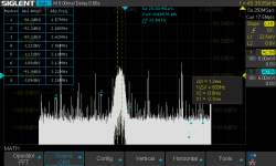
The following peaks seem to be consistent: 1.22 MHz, 1.57 MHz, 2.31 Mhz as regular peaks during any sound and with the CDP on pause, those seem to be present almost consistently. Unfortunately I don't have a signal generator other than the Mac at the moment nor a spectrum analyser (I have plans for both).


Zooming into the 1-4MHz region:


So that looks like there's some strong peaks at 1.57MHz, around 2.234-2.276 with some spikes at 2.08 and 2.42 MHz that seem to remain. This is with the case open. That 2.34-2.276 area rise gets into the 80dB on occasion.
So I think were are seeing some instability, close to the sim.
Zooming into the 1-4MHz region:
So that looks like there's some strong peaks at 1.57MHz, around 2.234-2.276 with some spikes at 2.08 and 2.42 MHz that seem to remain. This is with the case open. That 2.34-2.276 area rise gets into the 80dB on occasion.
So I think were are seeing some instability, close to the sim.
A while back I adapated/wrote a Software AWG for linux that allows the oscilloscope bode plot to control it. Take this with a punch of salt in that it's subject to the Mac mini's internal sound reproduction and filters.
The scope is repeatedly tracing the same shape so that's a good confirmation of the stability of the results. I've not turned up the amp completely hence it running at 8dB.

I'd love to have this as a proper AWG to perform accurate injection of 1V AC into the FB for example.
Edit - addition of a full power run simply by turning up the volume on the amp to max. The 8ohm 100W load resistors smell hot!

The scope is repeatedly tracing the same shape so that's a good confirmation of the stability of the results. I've not turned up the amp completely hence it running at 8dB.
I'd love to have this as a proper AWG to perform accurate injection of 1V AC into the FB for example.
Edit - addition of a full power run simply by turning up the volume on the amp to max. The 8ohm 100W load resistors smell hot!
Last edited:

I wouldn't put much trust in winding resistance (#18) as a guide to anything more than than the relative difference between each wire of the bifilar pairs on the same transformer. I've received a number of import orders from Element 14 (that's Farnell, now part of Avnet, to you guys) that were significantly different from one transformer to the other in qty 2 and that was because the same label manufacturer had simply used different winding wire gauges for the same spec. part. It makes datasheets a bit of a joke but that's what present day spare parts supply has become.
Last edited:
I took some measurements across resistors to calculate current at some spots of the original circuit yesterday.
With volume set to minimum, R115 (0.22ohm) shows it has an idle of 88mA across it.
Volume set to approx 1/4 so that the MC33079P outputs 2.5Vpp results in 44Vpp at the speaker out into an 8ohm load.
Volume set to max the MC33079P shows 13.5V and R115 shows peak of 7.42amps (15.84App).
The power supply rails have a 1.28Vpp 100Hz ripple, adding and additional 15mF per rail would be needed to reduce that further but the design should cancel some being push-pull. However I'm more concerned with the high frequency given there's no audible hum at listenable volumes and I suspect that would also change the character of the amp. Designed sag or simply cheap build - I'll let you decide 😀
So planned additions:
1. NOISE. I used a schaffner 394E-6-05-11 temporarily in the above post. I will replace the line inlet socket with a Schaffer FN9263 6A combined IEC, fuse and filter. This is short enough to fit in existing position without fouling the toroidal transformer. There is a difference in that the 394E has an inductor on the earth connection. The 2923 standard type rejection curves seem to fit the main areas of noise I'm seeing on the scope. It also targets the 1.54MHz noise well. I calculate a 4.5A max current draw from the amp, the 6A filter should cover that too. If I move up to the 10A version the dB reduction drops as the filter performance isn't as good.
The CDP has a CM choke, and it is designed to float - the IEC inlet socket has no earth pin. I could install an additional IEC inlet filter but I will check the noise first. That's a different thread.
2. Instability. I want to get the ltspice model closer to the measured amp as I feel that it's not performing as measured. Once I have that closer (not a precise match) then I'll be happier. I also need to educate myself more on the both miller compensation and feedback phase compensation. I understand the general principle but I need to understand so I can do some pen+paper maths. I have some TI and other guides to work through.
Sorry to distract from the original thread but I figured this info and possible fixes for some of the generic issues of the amp consolidated into this thread would be useful.
Why would silpads make them unstable? Sounds like bunk to me. It is best practice to ground the heatsink though, to stop it picking up RF which could get into the gate and make the devices oscillate. If that's a big problem, ferrites on the gate leads are the answer.Please check "revisiting lateral MOSFET stability" , I added additional details. The output devices appear to be just silpad mounted in the photos. The newer MOSFETs are difficult to make stable this way, they will need to be handled as described in the thread.
I've been reading up a bit (sorry if this is amateur interpretation).
There's two ways to solve the instability:
1. Miller compensation (think of this as forward compensation)
2. FB phase compensation (think of this as reverse compensation)
Miller compensation essentially puts capacitance between the gate and drain/source but requires a frequency dependant constant current source at the output.
Looking at the MF design I suspect the R121+C109 provides the frequency dependant 'source' in that it allows an easy path for that frequency. Thus then balances against the internal mosfet miller capacitance. Changing the resistor value here does alter the phase shift as you'd expect..
The FB phase compensation is through C104 and series 10K resistor?
I found a nice maths explaination, which ends up with a quadratic. Simple enough, and wiki has a easily digested explanation of separating the poles.
You can up the capacitor around TR106 to 470pF and drop the R121 and it starts looking better:


However I suspect the step response probably takes a dive! EDIT: yes - it's a disaster. Just hooking up the amp and scope to each of the TRs.
There's two ways to solve the instability:
1. Miller compensation (think of this as forward compensation)
2. FB phase compensation (think of this as reverse compensation)
Miller compensation essentially puts capacitance between the gate and drain/source but requires a frequency dependant constant current source at the output.
Looking at the MF design I suspect the R121+C109 provides the frequency dependant 'source' in that it allows an easy path for that frequency. Thus then balances against the internal mosfet miller capacitance. Changing the resistor value here does alter the phase shift as you'd expect..
The FB phase compensation is through C104 and series 10K resistor?
I found a nice maths explaination, which ends up with a quadratic. Simple enough, and wiki has a easily digested explanation of separating the poles.
You can up the capacitor around TR106 to 470pF and drop the R121 and it starts looking better:
However I suspect the step response probably takes a dive! EDIT: yes - it's a disaster. Just hooking up the amp and scope to each of the TRs.
Last edited:
Yep, upping that Miller cap to crazy levels will definitely make it stable - at the major cost of bandwidth. A square wave test will show you just how much that compromises the slew rate. The result is high THD.
The key with Miller compensation is just enough but no more than needed.
The values in the simulation I did were mostly arrived at by experimentation and guesswork... I don't have a head for the maths unfortunately!
Plotting V(OUT)/V(FB) is the usual way of getting the closed loop gain response. I generally optimise for widest bandwidth while keeping stability (phase >40degrees at gain = 0dB) and a decent margin (at least 20dB of margin preferably)
- Home
- Amplifiers
- Solid State
- Musical Fidelity A220 issue with hum on new output mosfets installed.