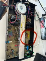
I guess the faulty is the right side, isn't true?
Please check TR6, TR8, I think that is wrong positioned. Are the plates of them looking at the right sides?
Please check TR6, TR8, I think that is wrong positioned. Are the plates of them looking at the right sides?
i will google it and try to test it your wayDBT = dim bulb tester. A mains filament bulb in series with the mains to limit current. An online search for 'dim bulb tester' will bring lots of info up
OK 🙂
Before you do it is worth checking R5 (22k). If this is high it would give a positive offset and no current in the output stage. If the offset was negative then check R12 (22k). Worth a quick look.
Before you do it is worth checking R5 (22k). If this is high it would give a positive offset and no current in the output stage. If the offset was negative then check R12 (22k). Worth a quick look.
i was near the point to throw it out of the window!
We're nowhere near the end of faultfinding on this one. We've looked at the obvious stuff and not found anything, now we have to get a bit more creative and isolate the problem initially to one area such as the output stage or the input stage or the current regulation (TR5 and 7) but do just look at those 22k's first.
Just by looking I recalled someone close to to me measuring a tube tape recorder every year and not finding the error. I once witnessed this and looked at him measuring. He flipped the device over and then I looked and told him he was measuring the good channel.
would be fun, but in this case it is really the bad side...
i wrote down the missing names on the PCB on the faulty side.
makes it a bit easier for me...

i wrote down the missing names on the PCB on the faulty side.
makes it a bit easier for me...
hi.We're nowhere near the end of faultfinding on this one. We've looked at the obvious stuff and not found anything, now we have to get a bit more creative and isolate the problem initially to one area such as the output stage or the input stage or the current regulation (TR5 and 7) but do just look at those 22k's first.
those 22k resistors measure fine (nearly 22k).
May I suggest recording voltages at the following points. They will give a good overview of the state of the bias and guide further measurements.
collector TR10
base TR3
base TR4
junction of R23 and C14
collector TR9
base TR1
base TR2
junction of R22 and C13
Please measure with black meter probe on circuit ground.
collector TR10
base TR3
base TR4
junction of R23 and C14
collector TR9
base TR1
base TR2
junction of R22 and C13
Please measure with black meter probe on circuit ground.
- Home
- Amplifiers
- Solid State
- Musical Fidelity A1 - Problem
