I've had this Pre from new and done quite a number of mods (500VA transformer, Panasonic Pot, Multicap Rtx and Sonicap Gen 1 caps) which have all improved the sound considerably. One problem with this pre-amp is noise from the Quad N-Channel mosfets ( ZVN4206E ( VQ1001J ) ). In an effort to eradicate this I bought some 2sk170's. At first I just did push fit into the left channel's i.c. socket. The good news was that the hiss was gone and volume level was just the same as the right channel. Unfortunately there was a slight hum/burble noise. At first I put this down to local pick-up due to lead length.
Next I cut back the lead lengths and soldered them direct into the pcb, left and right channels.
OK, so no background hiss, but I was left with what I would call a motor-boat type hum/burble equal to about "20 to" on the volume control. Turning up the volume produced a very clear sound except of course for this background hum.
Can anyone suggest what may be causing this?
My background is electronic repair not design.
Many thanks in advance.
Mike
Attachments
i too have this preamp. its very noisy yes. i rebuilt the mc stage using some paralleled ssm devices a few yrs ago, that cct is now very quiet.
can u tell me a bit more about the mods you have done? i too replaced all the electrolytics as they were old and leaky, but the design looks all ac coupled and uses a stack of expensive looking poly caps .
i have tried in vain to find those zvn4206 devices but couldnt.....
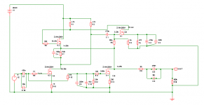
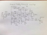
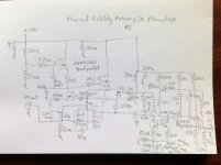
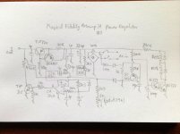
did you draw that diagram yourself? never been able to find schemis for much MF stuff. a very helpful guy on here has been helping me fix my power amp though 🙂
can u tell me a bit more about the mods you have done? i too replaced all the electrolytics as they were old and leaky, but the design looks all ac coupled and uses a stack of expensive looking poly caps .
i have tried in vain to find those zvn4206 devices but couldnt.....
did you draw that diagram yourself? never been able to find schemis for much MF stuff. a very helpful guy on here has been helping me fix my power amp though 🙂
Mike, I sent you a private message. The post is rather old but I am still interested. I think the diagram has some errors, so I'm curious if you actually tested or simulated the circuit or that you have drawn the diagram by looking at the pcb. Furthermore, I like to hear in what way you've changed the amp, what worked for you and what didn't?
By the way: the preamp hisses somewhat and that is by the nature of the mosfets themselves (in relation to topology used). Changing to BS170 won't change this, I actually tried it myself. Your motorboating issue is probably related to the feedback capacitor of 100p. Try to fiddle with this (make it bigger or smaller, try to leave it out altogether).
By the way: the preamp hisses somewhat and that is by the nature of the mosfets themselves (in relation to topology used). Changing to BS170 won't change this, I actually tried it myself. Your motorboating issue is probably related to the feedback capacitor of 100p. Try to fiddle with this (make it bigger or smaller, try to leave it out altogether).
This phenomenon (measuring badly, sounding okay) happens all the time and seems to be a hallmark of some of the older MF products. The A1 measures like a bad tube amp but it sounds like magic, so who cares. All Tim de Paracivini designs by the way. By contrast take the MF MVT preamp, which is designed by Dr Thomas (MVT for MV Thomas?) and of the same era (and very expensive at the time!), I don't know about the measurements, but it sounds more hifi and less euphonic. I have both original preamp at my disposal so I check this out every now and then.
yes i know this can be the case but i was shocked at just how bad it was for a preamp and at the ugly waveform on my scope (output from the distortion analyser).
inspired me to build a better one
inspired me to build a better one
Curious
Now you make me curious Raymondo! Would you share your journey to the better preamp with us? Did you find something that sounds at least as good (= somewhat euphonic I guess) but measures the lot too?
Now you make me curious Raymondo! Would you share your journey to the better preamp with us? Did you find something that sounds at least as good (= somewhat euphonic I guess) but measures the lot too?
I have the same preamp and yes, it does hiss a bit. Regarding changing electrolytics etc are there specific ones that have the biggest effect or just change the lot ?
I am toying with a battery psu in place of the std. I updated mine to an updated transformer and also added a lot of improved internal screened cable
Finally, I would like to improve the channel balance.. Could anyone make a recommendation ?
Thks
I am toying with a battery psu in place of the std. I updated mine to an updated transformer and also added a lot of improved internal screened cable
Finally, I would like to improve the channel balance.. Could anyone make a recommendation ?
Thks
Improve
Yes, it can make a difference to what electrolytics you use. But no general rules, just try some brand. MF did not use fancy stuff themselves, so I would not be too worried. The most important one soundwise is the 10mF at the output.
About channel balance. This has to do with the potentio meter only. Replace it with a new one (alps or whatever) and it should be better. But even expensive pots have problems when the preamp has too much gain in the lower regions. In that case you could try to change the gain factor of the preamp, it is now around 10 times (20 dB) and is determined by the feedback resistor of (from memory) 10k (you recognize this one by looking at the poly cap of 100pf that is in parallel with this resistor). Changing this value to 4k7 lowers the gain to around 4-5 times.
This is great advice thanks. I have not opened up my preamp in years.. Can you recall the value of the pot ! I assume its log type.
You mentioned the gain being too high.. I assume you mean the total gain ? Where might I find the resistor you mentioned ? Surely another way to do this is to add some resistance into the volume circuit ?
Finally, regarding the output cap.. Change to polypropylene ? Does the value affect the bass output ? Keep the value the same ?
Thks
(2)
- value pot: 50k or 100k log.
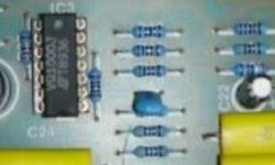
- resistor: see attachment, the 100pf is the small blue cap, I think it is the resistor just below the blue cap, check the value, must be around 10k, try putting another 10k over this resistor to get 5k new value.
- alternative: you could use a voltage divider just after the pot, but is more complicated
- MKP: you could try that, there is plenty of room inside the case, I would keep the value the same at 10uF. But not a problem to go as low as 1uF. It will affect bass response below 20hz (depends on load of power amp) but improbable that you could hear that. Just try.
- value pot: 50k or 100k log.
- resistor: see attachment, the 100pf is the small blue cap, I think it is the resistor just below the blue cap, check the value, must be around 10k, try putting another 10k over this resistor to get 5k new value.
- alternative: you could use a voltage divider just after the pot, but is more complicated
- MKP: you could try that, there is plenty of room inside the case, I would keep the value the same at 10uF. But not a problem to go as low as 1uF. It will affect bass response below 20hz (depends on load of power amp) but improbable that you could hear that. Just try.
Attachments
Thats brilliant advice - thanks a lot. I have to ask, how come you know this strange preamp so well ?
I was curious about the good sound and the hiss. I tried to rebuilt the circuit by myself to try out different power supply arrangements and different mosfets like bs170. In this way you can learn a lot while not destroying the original.
Hi Colin... thanks for posting these drawings. I'm curious to know how you might implement a simple balance control on the pre-amp. I'm suffering imbalance (only slight mind you)
Also, regarding the main output cap (10mf).... what issues do you see in replacing with (say) 5mf ? Any improvement in the bass ?
What type do you recommend ?
Rgds
Also, regarding the main output cap (10mf).... what issues do you see in replacing with (say) 5mf ? Any improvement in the bass ?
What type do you recommend ?
Rgds
Hi Steve,
The 10uf output cap was probably made to be such a large value because it is a cheap electrolytic, with attendant higher distortion. Depending on the input impedance of your power amp you could use a good quality film 1uf cap. With say 100k poweramp input impedance the bass roll off would still only be 2.3 hz. For the balance control, you could use an alps balance pot and put it electrically after the volume pot, in series with the 39 ohm resistor.
Regards
Hi Colin
Is that output capacitor a reversible electrolytic or is it polarised ? (it shows on your diagram as polarised)
In fact, does it matter ?
Thanks
Steve
Is that output capacitor a reversible electrolytic or is it polarised ? (it shows on your diagram as polarised)
In fact, does it matter ?
Thanks
Steve
It's a standard cheap polarised one. You can try anything between 1uF and 10mF as you like. I've tried a lot including boutique caps but am back now to the standard cap. Just listen and choose as you please. In the old days it was a sin to listen to cheap electrolytics but to be honest I like them a lot, it gives the music a flowing and easy-going quality (good be my ears/age, could be that the quality of electrolytics has improved a lot, I don't know).
- Status
- Not open for further replies.
- Home
- Amplifiers
- Solid State
- Musical Fidelity 3A Pre-amp background hiss