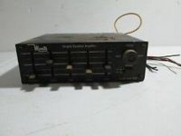
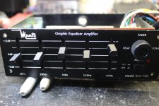
I am trying to resuscitate a MUNTZ AM-160 EQ Power Booster from 1977 I believe.
I wonder if anybody here might be of help with any info, literature, schematic etc. Flying blind here and really just want to get this thing working again. RELIC from the past. It blew a MAIN OUTPUT TRANSISTOR as well as a couple others in line. Any input is appreciated. THANKS BDBD/2022
I wonder if anybody here might be of help with any info, literature, schematic etc. Flying blind here and really just want to get this thing working again. RELIC from the past. It blew a MAIN OUTPUT TRANSISTOR as well as a couple others in line. Any input is appreciated. THANKS BDBD/2022
Attachments
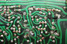
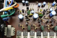
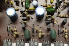
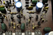
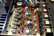
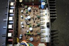
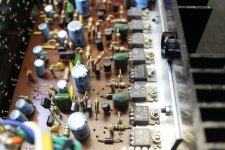
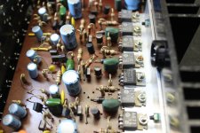
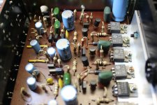
Hi Perry.... sorry.... I seriously do not wish to be a pain... WELL I read your site over and over... I am slowly getting it. Heres a HEAD scratcher... I read a RESISTOR coming off the large blue caps on 3 of the circuits.... But ONE for some reason goes INSTEAD to the POSITIVE terminal of the large blue cap in its "space". I can "see" 4 separate amplifiers that combine eventually to leave the FADER as TWO channels (L&R) Fader does the fading. it has a COOLING FIN so its a hot runner. I have IDENTIFIED (3) bad transistors, ONE Main which I replaced barely, this BOARD is BRITTLE in them HOT SPOTS I am finding. burned and corroded so am JUMPING.... Ugggggggg not too pretty BUT its connected. I foresee more JUMPERS. more Uggggggg.... OK, I am at this PHASE checking for ANYTHING out of the NORMAL in EACH of them amplifier GROUPINGS. 3 of them seem KOSHER... all the same. Its the ONE in the center You can see the + and - markings on the BOARD for the CAPS. As you can see the RESISTOR (in BLACK MARKER) all go to the NEGATIVE except for that one channel that BLEW It appears. Its where I am at right now, waiting for TRANSISTORS in the mail.... HERES PICS.... Sorry again... RELIC BOY.... BDBD/2022
Attachments
-
 IMG_0195.JPG523.6 KB · Views: 76
 -
 IMG_0196.JPG650 KB · Views: 71
 -
 IMG_0197.JPG583.9 KB · Views: 72
 -
 IMG_0198.JPG544.5 KB · Views: 73
 -
 IMG_0199.JPG278.1 KB · Views: 67
 -
 IMG_0200.JPG519.8 KB · Views: 80
 -
 IMG_0201.JPG451.8 KB · Views: 67
 -
 IMG_0202.JPG398.1 KB · Views: 73
 -
 IMG_0203.JPG456.7 KB · Views: 70
 -
 IMG_0204.JPG304.5 KB · Views: 79
 -
 IMG_0205.JPG286.6 KB · Views: 84
 -
 IMG_0206.JPG284.3 KB · Views: 72
 -
 IMG_0207.JPG294.2 KB · Views: 79
 -
 IMG_0208.JPG381.7 KB · Views: 80
 -
 IMG_0209.JPG280.9 KB · Views: 82
 -
 IMG_0210.JPG331.6 KB · Views: 84
 -
 IMG_0211.JPG328.6 KB · Views: 75
 -
 IMG_0212.JPG329 KB · Views: 78
 -
 IMG_0213.JPG322.7 KB · Views: 79
At this point, does any channel produce audio?
Are all of the 2sc outputs insulated from the heatsink?
Are all of the 2sc outputs insulated from the heatsink?
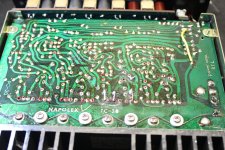
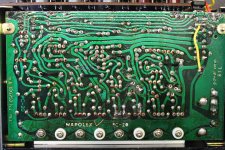
Hi Perry.... sorry.... I seriously do not wish to be a pain... WELL I read your site over and over... I am slowly getting it. Heres a HEAD scratcher... I read a RESISTOR coming off the large blue caps (220uf) on 3 of the circuits.... But ONE for some reason goes INSTEAD to the POSITIVE terminal of the large blue cap in its "space". I can "see" 4 separate amplifiers that combine eventually to leave the FADER as TWO channels (L&R) Fader does the fading. it has a COOLING FIN so its a hot runner. I have IDENTIFIED (3) bad transistors, ONE Main which I replaced barely, this BOARD is BRITTLE in them HOT SPOTS I am finding. burned and corroded so am JUMPING.... Ugggggggg not too pretty BUT its connected. I foresee more JUMPERS. more Uggggggg.... OK, I am at this PHASE checking for ANYTHING out of the NORMAL in EACH of them amplifier GROUPINGS. 3 of them seem KOSHER... all the same. Its the ONE in the center You can see the + and - markings on the BOARD for the CAPS. As you can see the RESISTOR (in BLACK MARKER) all go to the NEGATIVE except for that one channel that BLEW It appears. Its where I am at right now, waiting for TRANSISTORS in the mail.... I put RED DOTS on all the transistors and BLACK LINES over the resistors in question. HERES PICS.... Sorry again... RELIC BOY.... BDBD/2022
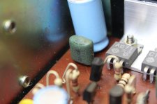
OK... I get SOUND AMPLIFIED on both channels, so I believe the ON/OFF SWITCH is not the issue I think. It powers up QUICKLY but then sorta FADES away then qradully it comes alive. I noticed a MAIN TRANSISTOR was getting HOT and it showed signes of cracking so I replaced it BUT still not HAPPY so I search... FOUND a BURNED transistor as well as the one next to it gave bad readings compared to them others so OUT they came. Small D468 model type. I checked ALL the MAIN POWER TRANSISTORS, they were LOOSE throughout so I gave em a good tightening and they all appear to be good, no shorts now and no problems with power or grounds. ALL INSULATED... and the ones to GROUND read ground. BDBD/2022At this point, does any channel produce audio?
Are all of the 2sc outputs insulated from the heatsink?
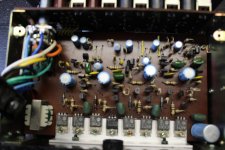
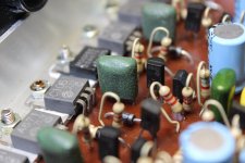
At THIS POINT I have them D468 transistors on order and in the mail soon. 2 of them it appears are bad. I put red dots on the transistors so I could check them and they appear to be unaffected by the BURN OUT. I test for any DIFFERENCES in the circuits... PARITY so..... It SEEMS that there should be 2 amplifiers that go to the NEGATIVE pole and perhaps 2 amplifiers that go to the POSITIVE pole. INSTEAD I have 3 amplifiers that read negative at the resistor and ONE amplifier reading ZERO.... cause the resistor is attached instead to the POSITIVE pole of the correlating Cap (220uf).... I dont get it but a designer might.... maybe a PROTECTION aspect.... Cant wait to get them transistors in the mail and SEE what happens...... SMOKE... or SUCCESS!!!!...... Been smoky around here as of late. BDBD/2022
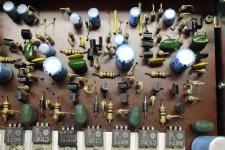
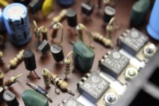
oh yeah, one more thing them GREEN POLY caps... Cracked and POWDERY... Ugggggg I struggle with a PART NUMBER as they are surely in need of replacement.... Cant see the number... Uggggggggg Schematic in need.... Maybe an UPGRADE SCHEME.... Superior parts in that spot. NAPONEX today makes stuff for Disney.... 1977 was a LONG time ago it appears. Might not be the same company today. No help there. Oh well. BDBD/2022
Attachments
Do any of the tabs of the 2SC transistors on the heatsink have Zero resistance to the heatsink?

as the heatsink goes I read ground on 4 and none on 4., (positive) Numbers (L to R) 1,3,5,7 are mounted to the heatsink ground and numbers 2,4,6,8 are INSULATED, no shorts present. I get somewhat uniform readings on each of them sets BUT one set is somewhat different than the other BUT they all are within the same grouping as readings go, quite uniform. grounded ones read in the 600 range, positive ones in the 900 range throughout using the diode checker mode on my tester. OK...BDBD/2022
one more thing.... theres a TERM....... MUNTZING.... its a word describing what Earl MADMAN MUNTZ would do to a TV set. He would PULL stuff OUT of the completed set till it STOPPED WORKING, then he would replace that last part and THERE YA HAVE IT..... a "MUNTZED" circuit layout was born. LOL.... MADMAN. I own the LARGEST collection of MAD Magazine collectables outside the USA.... I was raised on MAD. BDBD/2022as the heatsink goes I read ground on 4 and none on 4., (positive) Numbers (L to R) 1,3,5,7 are mounted to the heatsink ground and numbers 2,4,6,8 are INSULATED, no shorts present. I get somewhat uniform readings on each of them sets BUT one set is somewhat different than the other BUT they all are within the same grouping as readings go, quite uniform. grounded ones read in the 600 range, positive ones in the 900 range throughout using the diode checker mode on my tester. OK...BDBD/2022
one more thing.... theres a TERM....... MUNTZING.... its a word describing what Earl MADMAN MUNTZ would do to a TV set. He would PULL stuff OUT of the completed set till it STOPPED WORKING, then he would replace that last part and THERE YA HAVE IT..... a "MUNTZED" circuit layout was born. LOL.... MADMAN. MAYBE this circuit is MUNTZED?.... MADE to SELF DESTRUCT....... Seems the channel that BLEW is the same one with that resistor/cap discrepancy... Hmmmmmm.... I own the LARGEST collection of MAD Magazine collectables outside the USA.... I was raised on MAD. BDBD/2022
Ok.... as you mention Perry.... STARE at the circuit board and try to learn the circuit.... It APPEARS the one side of the construct goes to the NEGATIVE poles on the main switch and the other side goes to the POSITIVE poles through the FADER. I am SUPPOSING the VARIATION in circuit in half the NEGATIVE SIDE is due in part to the FADER on the other amps. Fader must introduce dynamics that dictated a different layout on the negative sides of the amp. Good as I got thus far. Waiting for transistors in the mail. SOON will see. Hope it comes back to life. RARE RELIC. BDBD/2022
The circuit is simple. Why not draw out a diagram, either by hand or using something easyEDA? If you do repairs, this is something that you'll have to do sooner or later.
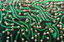
The circuit is simple, but deciphering that tangle of traces will be fun. I would take that picture of the solder side, enhance the contrast as much as possible, reverse it, and print it out at lower contrast (traces in grey). Then draw in the components, and highlight the ground and power traces. Number all the components (R1, Q1, C1, D1...). Then start drawing it as a schematic on a big sheet of paper. Or, create a netlist, and maybe a schematic CAD program will do the work for you. A netlist is a good idea anyway, since it's useful for verifying the schematic and layout. If you do go through all that work, please share the schematic somewhere for the benefit of future generations.
Yeah... I will do that... Create a schematic. TODAY I got A transistor in the mail. Was SUPPOSED to be THREE..... Guy sent me one WRONG transistor as well as a small transformer?.... My goodness. SO I looked it up, that wrong transistor is right NPN ways but poles reversed and ut appears to be within operating conditions so I popped it in backwards. Put the other one in correct. Thay appear to be working fine now. The amp still appears to have problems though, GRAVELLY sound, sorta distorted, a bit more on one channel it sounds. IT WORKS now, no HOT parts and ran for several hours just because. I am wondering if the capicitors are the culprit at this juncture so... I think I will buy a small set of caps... a variety box. Still fooling around with this RELIC.....
LABOR OF LOVE
BDBD/2022
LABOR OF LOVE
BDBD/2022
Bad sound on both channels suggests there's one common fault, like a voltage regulator that's starving them of voltage. Or maybe a bad cap is pulling the voltage down somewhere (I've seen one behave like a resistor in a Pioneer receiver)? Maybe follow your hunches and desolder components one at a time and check them with a component tester (like a $20 "transistor tester" from China).
Good luck; it sounds like you are making progress. I was tempted to suggest that you just give it a wipe down and put it up on a high shelf as a historical relic, but it would be cool for it to live again in a classic car or as part of workshop sound system.
Good luck; it sounds like you are making progress. I was tempted to suggest that you just give it a wipe down and put it up on a high shelf as a historical relic, but it would be cool for it to live again in a classic car or as part of workshop sound system.
Last edited:
Thanks and YES... its here in the Land of Aloha for good reason. I have currently ONE "good" channel NOW.... and one still somewhat distorted. Both channels work, just the one now is still distorted. I STARTED with replacing them cracked POLY caps, they were all over the place but one so they needed replacement, BUT.... no real noticeable change in the output SO... on to ELECTROLYTICS... Changed the 4 220 uf caps... still no real difference SO change them 8 smaller ones and YAY...... one side came to LIFE... other side though still distorted. Getting close to success so I THINK it MIGHT be them 2 CERAMIC caps... and maybe them other 4 there SO.... Buy another assortment of caps.... In the mail today. SLOW PROGRESS is PROGRESS... I take it slow, in stages to see what the changes produce... I understand the shotgun method is frowned upon so... Heres my SCHEMATIC so far... SOON I will overlay the top of the board and all the components will be transparent/visible. FUN FUN FUN... BDBD/2022Bad sound on both channels suggests there's one common fault, like a voltage regulator that's starving them of voltage. Or maybe a bad cap is pulling the voltage down somewhere (I've seen one behave like a resistor in a Pioneer receiver)? Maybe follow your hunches and desolder components one at a time and check them with a component tester (like a $20 "transistor tester" from China).
Good luck; it sounds like you are making progress. I was tempted to suggest that you just give it a wipe down and put it up on a high shelf as a historical relic, but it would be cool for it to live again in a classic car or as part of workshop sound system.
Attachments

The circuit is simple. Why not draw out a diagram, either by hand or using something easyEDA? If you do repairs, this is something that you'll have to do sooner or later.
Attachments
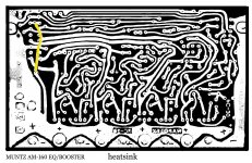
The circuit is simple, but deciphering that tangle of traces will be fun. I would take that picture of the solder side, enhance the contrast as much as possible, reverse it, and print it out at lower contrast (traces in grey). Then draw in the components, and highlight the ground and power traces. Number all the components (R1, Q1, C1, D1...). Then start drawing it as a schematic on a big sheet of paper. Or, create a netlist, and maybe a schematic CAD program will do the work for you. A netlist is a good idea anyway, since it's useful for verifying the schematic and layout. If you do go through all that work, please share the schematic somewhere for the benefit of future generations.
Attachments

- Home
- General Interest
- Car Audio
- MUNTZ AM-160 Equalizer Amplifier from 1977, need schematic.