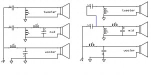
In the picture bellow you will find a simplified schematic of a 3Way xover of second order
The left approach is the more classic while in the right approach which i have seen in a few manufacturers, tweeter network is fed from the mid xover at the point where already mid net work cleared out all the bass
from electrical POV obviously the tweeter network will have a far easier job to do since most of the job is done by the mid network
That's it ? i don't think so
so please comment with pros and cons and why
thank you
Attachments
The first schematic will lead to phase issues between tweeter and midrange. It is the wrong approach.
I'm only half awake as I'm down with (another) ear infection & had a rotten night, but there shouldn't be any real difference assuming the series cap in the HF unit is selected to provide the desired value, since it's become a compound of itself and the series cap on the midrange. If each were 10uF, the effective value for the HF leg is 5uF & so on & so forth.
First you mean the left ?The first schematic will lead to phase issues between tweeter and midrange. It is the wrong approach.
Yes, the one on the left is wrong.
Scottmoose: there is a difference in phase response of the tweeter signal, I am sure you can map it out for yourself. But the gist of it is that the tweeter high pass section needs to receive the same phase shifted signal as the low pass section of the mid.
Scottmoose: there is a difference in phase response of the tweeter signal, I am sure you can map it out for yourself. But the gist of it is that the tweeter high pass section needs to receive the same phase shifted signal as the low pass section of the mid.
I agree with vacuphile, use the schematic on the right. It allows standard calculations for the component values to be made without correcting for interaction between them and it also offers a higher rate of roll-off for the treble section.

Yes, this always seemed a compelling concept. Especially the idea that down low the tweeter gets even better protected from excursion.
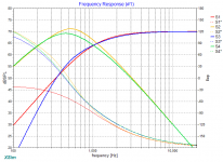
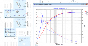
Each method could be made to support more or less the same result if you wanted to sit down and work out some values, certainly the exact result could be produced with any number of topologies. That said, here is a sim of LR2@1k, vs the same with an additional LR2@250Hz intruding on it.
Each method could be made to support more or less the same result if you wanted to sit down and work out some values, certainly the exact result could be produced with any number of topologies. That said, here is a sim of LR2@1k, vs the same with an additional LR2@250Hz intruding on it.
Attachments
Hmmm looking at it from a purely electrical standpoint, it seems to be that on the left you have 2nd order on woofer, mid and tweeter, typically in that configuration (assuming acoustically it worked out right with phase) you would flip the midrange.
The one on the right is 2nd order woofer and mid and 4th order on the tweeter (I honestly hadn't thought about doing this before, but I guess with my hybrid setup I already have this to a degree (active cross for woofer with the high pass feeding both the mid and the tweeter which have a passive crossover).
At the end of the day you need to consider what the acoustic transfer function is, as what you do electrically is only part of the story
Tony.
I'm obviously missing something obvious here, because looking at that second [right hand] diagram, I'm seeing an HF circuit comprised of two capacitors in series (the initial midrange cap, followed by a second cap in the nominal HF branch), which are followed by a shunt inductor. I can't see any other components in that HF leg, so as far as I can tell, that makes a 2nd order electrical high pass, the series capacitance total Ct being the usual derivation of Ct = (C1*C2)/(C1+C2). Can somebody point out what my sleep-deprived mind is completely missing?
Last edited:
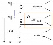
I saw the same at first but try moving the junction to the other side of the coil and you should see it. The coil is in shunt so it doesn't matter which side of the branch the take off is, but that should make you see it differently 🙂
edit: added edited diagram to make it clear.
Tony.
edit: added edited diagram to make it clear.
Tony.
Attachments

Last edited:
No, you are seeing it correctly.I'm obviously missing something obvious here, ...
It's just a second order low pass with the C being two caps in series. I have seen this done a few times in vintage gear from the 50s-60s like stereo consoles. The tweeter cap is fed off the midrange cap, sometimes with a shunt inductor, sometimes not. It's not something we'd do today, but seems to have been fairly common half a century ago.
The first schematic will lead to phase issues between tweeter and midrange. It is the wrong approach.
How do you know that? You don't know the phase response of the "drivers", so you cannot make any kind of statement about the overall phase of drivers plus crossover elements.
A driver is not a resistor!
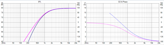
It's interesting that you say that, although my take on it is a little different. Firstly, the main apparent difference in response is the steepness of the tweeter at lower frequencies. The mid peaking can simply be ironed out in the details. I used a 2.5 octave bandpass for the mid.Yes, the one on the left is wrong.
- image 1
orange and red, normal topology
green and blue, piggybacked tweeter
Phasewise (and I reversed the tweeter in all cases), they all come close near the cross. It's lower down that the red one (normal tweeter connection) stands out, even though it's the typical 2nd order on its own. In both cases the mid shifts more due to the bandpass, and the tweeter goes there too due to the steeper rolloff.
- image 2, adds phase
Attachments

No, you are seeing it correctly.
It's just a second order low pass with the C being two caps in series. I have seen this done a few times in vintage gear from the 50s-60s like stereo consoles. The tweeter cap is fed off the midrange cap, sometimes with a shunt inductor, sometimes not. It's not something we'd do today, but seems to have been fairly common half a century ago.
Thank goodness for that, I was worried I was losing the plot completely. Although granted, some might wonder (with reason) if I ever had it in the first place... 😉
I saw the same at first but try moving the junction to the other side of the coil and you should see it. The coil is in shunt so it doesn't matter which side of the branch the take off is, but that should make you see it differently 🙂
edit: added edited diagram to make it clear.
Tony.
Absolutely Tony: I simply meant that as originally drawn, the circuit doesn't do that. To obtain the 4th order electrical HP you have to change the circuit topology as you re-drew it. That latter would certainly be a useful approach if the necessary values lined up, as well as providing a good saving on parts.
Last edited:
No, Tony's right here. The nodal junction of the 2 caps and coil is third electrical, and the tweeter has another coil. The attachment fore or aft is still the same electrical connection.
Back when this was more popular, there would not be a shunt coil on the mid and just high passed with a cap. This would then do as Scott suggests.
Later,
Wolf
Back when this was more popular, there would not be a shunt coil on the mid and just high passed with a cap. This would then do as Scott suggests.
Later,
Wolf
I can see the inductor in the mid section affecting the tweeter and making for a steeper roll-off.  I'm more used to the "cap only" version of this.
I'm more used to the "cap only" version of this.It's funny how our brains are conditioned to the way things are normally drawn.
The potential difference between point A and point B provided decent gauge wire is used (or decent sized tracks on a PCB will likely be in the uV range. Yet our brains tell us that when connected to A it is a different circuit to what it is when connected to B. Clearly it is the same thing just drawn differently 🙂 If you remove the stuff in the orange box, it should be even more clear.
Tony.
Attachments
- Home
- Loudspeakers
- Multi-Way
- Multiway xover question