Multiple Faital Pro 3fe25 Back loaded horn
Hi at all, i have a dude.
If i use six or eight Faital Pro 3FE25 per Back loaded horn, could i have some problem of dispersion or comb filter ?
Only until 1,8kz frequency..
Santiago
Hi at all, i have a dude.
If i use six or eight Faital Pro 3FE25 per Back loaded horn, could i have some problem of dispersion or comb filter ?
Only until 1,8kz frequency..
Santiago
Attachments
Find the longest center to center [ctc] spacing to find the 1 WL XO limit with the understanding that it ideally needs to be a 1/4 WL.
For example: it's 20 cm, then 34400/20 = 1720 Hz 1W or 430 Hz 1/4 WL.
Or if 1800 Hz is the limit, then 34400/1800 = 19.11 cm or 4.78 cm.
Note that normally 1/3 WL is acceptable, most commonly used.
GM
For example: it's 20 cm, then 34400/20 = 1720 Hz 1W or 430 Hz 1/4 WL.
Or if 1800 Hz is the limit, then 34400/1800 = 19.11 cm or 4.78 cm.
Note that normally 1/3 WL is acceptable, most commonly used.
GM
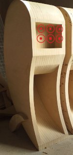
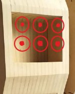
Ok , i use 4 drivers , the center of the cones could be at 4.8cms !!
But with 3 colums of two drivers , the distances of cones will be differents between them.
But with 3 colums of two drivers , the distances of cones will be differents between them.
Attachments
I believe probably in the original equation they assume a point source. At s distance L apart. However in this case I believe it is a full cone I don't think the equation is valid anymore. All the cones are moving together as if it is one big diaphragm, I don't there will be a combing effect...
But with 3 colums of two drivers , the distances of cones will be differents between them.
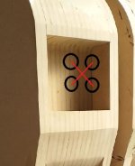
Need to draw a diagonal line.
Again, I posted: "Or if 1800 Hz is the limit, then 34400/1800 = 19.11 cm or 4.78 cm."
So based on a 4.8 cm ctc spacing, you're limited to two rows of three at ~0.794 WL ctc.
GM
I believe probably in the original equation they assume a point source. At s distance L apart. However in this case I believe it is a full cone I don't think the equation is valid anymore. All the cones are moving together as if it is one big diaphragm, I don't there will be a combing effect...
It's valid TTBOMK. They're moving as one down low, but as the frequency increases they become increasingly more independent of each other with obvious combing effect above the ~1 WL point, though this is so dependent on each human's hearing acuity, room, listening distance, etc., like a MTM or line array that it's strictly a guideline.
That said, I've wondered if an average is a better way, i.e. [4.8*9.6]^0.5 = ~6.79" in which case we could just fudge a bit and use 2 rows of four [19.11/4.8 = 3.98].
GM
Try 5 with one in center of square. Like a 5 on a game die.
Series/parallel with 5 is tricky. Or use 5 parallel 16ohms for about 3ohm load assuming amp can handle that.
Series/parallel with 5 is tricky. Or use 5 parallel 16ohms for about 3ohm load assuming amp can handle that.
maybe i need to stop imbibing scotch today, but with arrays depending on layout wouldn't frequency shading make for a listenable speaker?
maybe i need to stop imbibing scotch today, but with arrays depending on layout wouldn't frequency shading make for a listenable speaker?
I do not understand you!!
Alcoholic musings 😉 referring to a type of array tuning, something you may find of use.
frequency shading - Google Search
GM
frequency shading - Google Search
GM
Multiple drivers create comb filtering. As our ears are in the horizontal plane, we are much more sensitive to comb filtering from multiple sources in the horizontal plane.
If I had to use multiple drivers in a horizontal plane I would do it like Tecton.

Maybe mount he middle driver or middle line of drivers a little bit forward so that the driver frames overlap and CTC distances gets smaller, and this will also influence directivity. (getting wider)
About the tecton array Help Understanding Tekton Tweeter Array Schematic?
If I had to use multiple drivers in a horizontal plane I would do it like Tecton.
Maybe mount he middle driver or middle line of drivers a little bit forward so that the driver frames overlap and CTC distances gets smaller, and this will also influence directivity. (getting wider)
About the tecton array Help Understanding Tekton Tweeter Array Schematic?
Last edited:
Alcoholic musings 😉
ok yeah i resemble that remark...and sorry for butting in but felt it necessary...everyone seemed to be quick to talk about the problems of comb filtering rather then offer up potential solutions.
I do use comb filtering as an advantage by putting them in a vertical line to narrow vertical directivity so they match a line tweeter like a ribbon, planar or AMT very well. Big advantage of this design is great horizontal off axis response and minimal floor and ceiling reflections.
Every single driver produces comb filtering relative to its diameter that starts at wavelength equal to its diameter; that is what makes the narrowing directivity for the higher frequencies it produces.
Or that is why smaller drivers have better off axis response for higher frequencies.
Great video about line source and line array speakers: YouTube
ok yeah i resemble that remark...and sorry for butting in but felt it necessary...everyone seemed to be quick to talk about the problems of comb filtering rather then offer up potential solutions.
No need, it's part of the whole; personally ran out of time to post more re layout.
GM
- Status
- Not open for further replies.
- Home
- Loudspeakers
- Full Range
- Multiple Faital Pro 3fe25 Back loaded horn