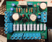
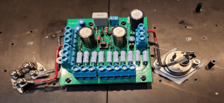
would you please share the mouser or digkey 3W,0.22R resistor link?thanksAmp boards assembled.
nothing at Mouser
at digikey
https://www.digikey.ca/en/products/detail/panasonic-electronic-components/ERX-3SJR22V/3982890
at digikey
https://www.digikey.ca/en/products/detail/panasonic-electronic-components/ERX-3SJR22V/3982890
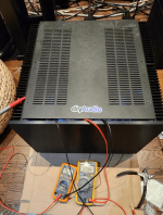
Power on without SIT and NMos. Bias preset.
48VDC on, no smoke. Adjusting RV1, G of SIT terminal block around 22.5V. Applying 1.3VDC on S of NMos terminal block, simulating 2A bias, adjusting RV2 the voltage G of NMos terminal block to around 5.5V.
48VDC on, no smoke. Adjusting RV1, G of SIT terminal block around 22.5V. Applying 1.3VDC on S of NMos terminal block, simulating 2A bias, adjusting RV2 the voltage G of NMos terminal block to around 5.5V.
Attachments
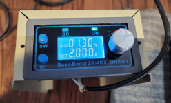
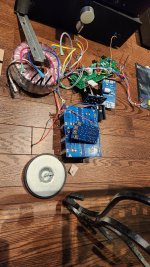
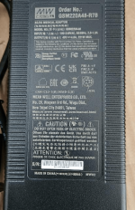
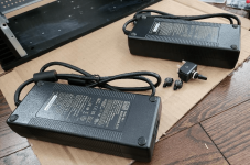
From the beginning, considering the case I have and copying Papa’s Sony V-fet, a single 48VDC power supply and around 2A bias is in mind. Checked all Mean Well 48VDC adapters, found the V- is not connected to Safe earth in its medical model GSM. All GST model including what is used in the Sony VFet has it V- connected to the earth. Two GSM220A48-RB7 are selected for the power. They are expensive.
Attachments


when started this build, one goal is clearly set: the amp has to have same measured signature as Papa's SIT model. that means similar THD and 2nd is dominant(negative, as Pa' often says)
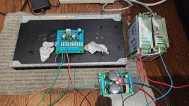
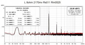
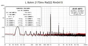
picture 1 to 4, speaker negative terminal connected from top(close to S of NMOS) to bottom (close to GND).
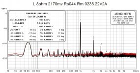
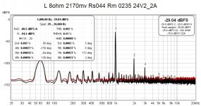
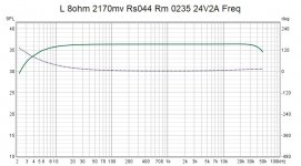
Rs/Rm = 0.11/0.565ohm, 0.22/0.445ohm, 0.33/0.335ohm, 0.44/0.235ohm, Iq=2A, SIT Vds=24V at 2.17Vrms output(max I can get with Focusrite) and 8ohm load.
It is very clear that THD is 2nd at +89. The 3rd is 20db lower than 2nd. the speaker- terminal goes from up to low, THD reduces slightly. the minimal 3rd is around 50%/50% Rs/Rm.
The THD number is very close to Pa's number.
picture 1 to 4, speaker negative terminal connected from top(close to S of NMOS) to bottom (close to GND).
Rs/Rm = 0.11/0.565ohm, 0.22/0.445ohm, 0.33/0.335ohm, 0.44/0.235ohm, Iq=2A, SIT Vds=24V at 2.17Vrms output(max I can get with Focusrite) and 8ohm load.
It is very clear that THD is 2nd at +89. The 3rd is 20db lower than 2nd. the speaker- terminal goes from up to low, THD reduces slightly. the minimal 3rd is around 50%/50% Rs/Rm.
The THD number is very close to Pa's number.
Attachments

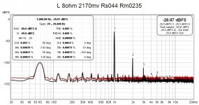
the influence of bias current
from left to right, Iq=1.8A, 2A, 2.2A, Vds 24V, Rs/Rm=0.44/0.235ohm, 2.17Vrms at 8 ohms.
THD reduces slightly with a decreasing Iq. 2A Iq has minimal 3rd at the testing conditions.
from left to right, Iq=1.8A, 2A, 2.2A, Vds 24V, Rs/Rm=0.44/0.235ohm, 2.17Vrms at 8 ohms.
THD reduces slightly with a decreasing Iq. 2A Iq has minimal 3rd at the testing conditions.
Attachments


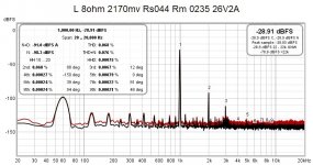
the effect of SIT Vds.
from left to right, Vds=22V, 24V, 26V. Iq=2A, Rs/Rm=0.44/0.235ohm, 2.17Vrms at 8 ohms.
Increasing Vds reduces THD, but still minimal 3rd is around 24V Vds.
from left to right, Vds=22V, 24V, 26V. Iq=2A, Rs/Rm=0.44/0.235ohm, 2.17Vrms at 8 ohms.
Increasing Vds reduces THD, but still minimal 3rd is around 24V Vds.
Attachments


The DIY of Papa's SIT MUFF has got what I wished, at least in design and engineering the PCB board I used.
The pw is very excellent for the amp, too.
As promised, I post the zipped whole KiCad project for the amp and power PCB here.
The pw is very excellent for the amp, too.
As promised, I post the zipped whole KiCad project for the amp and power PCB here.
Attachments
- Home
- Amplifiers
- Pass Labs
- Multi Configurable Testing PCB for Papa’s SIT-PMosfet, SIT-NMosfet MUFF and DEFiSIT Amplifier