Okay, so if my gain is 314 and 15.8 it would be 20log(314/15.8) = about 26db?? Seems very high.

smbrown,
You had a gain of 315 without feedback. That seems high.'
Bill,
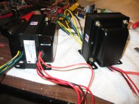
Your build looks very good. You may have to rotate your OPT if you find hum an issue. I like that you have the input and LTP far away from the PT and choke.
You had a gain of 315 without feedback. That seems high.'
Bill,
Your build looks very good. You may have to rotate your OPT if you find hum an issue. I like that you have the input and LTP far away from the PT and choke.
What's your final thoughts Sam?
I finally got through this thread and I was hoping to get a little more information on the sound. Sam how do you like it? You said the gain seems
to be a little high. How does it sound to you?
Bill did you ever finish it yet? Your build looks great.
One question for you guys. I have two James 5k 6255HF 50W output transformers. Would these work for this build or are they to small? I was going to put them in my current amp, but this thread got me thinking.
I have two James 5k 6255HF 50W output transformers. Would these work for this build or are they to small?
Unfortunately, the James trafos are too small for use with a KT88 Mullard setup. Remember, the O/P trafo is inside a GNFB loop and magnetic headroom is essential. You could use Mullard style circuitry with your "iron" in combination with EL34 family tubes. The yield would be approx. 35 WPC.
Okay, so if my gain is 314 and 15.8 it would be 20log(314/15.8) = about 26db?? Seems very high.
I did not check the 314 figure, but regarding 26db of NFB, that is not unduly high. Most of the famous Leak amplifiers used that: the Mullard 5-20 could stably work with up to 30dB.
Point is to check for possible instability at band ends. Perhaps old hat around here, but the easiest way for h.f. is by a square wave, determining where if any there are peaks (those would be way above the audio band at around 60 - 120kHz, but still be important for NFB stability. Remember the loudspeaker can be a very reactive load!) This performance would be totally dependant on the output transformer, so no advice to be given off-the-floor.
Should you feel uncomfortable, bring the NFB down to 20dB; no circuit in front of me now to advise.
Actually, I ended up removing the negative feedback all together. I also triode wired the EF86. There is still a ton of gain, but the addition of a volume pot solves that. The amp is dead quiet and with out the NFB, sounds more open and less congested, as you might expect. All in all, probably the best PP amp I've heard. I'm still playing with the idea of putting in 300b's but the B+ would have to be reworked some (cathode bias would take up some of the extra).
smbrown,
Your comment on limiting ther NFB is spot on with my observastions. I use a diffent input tube but have really limited the use of NFB as well. These are good sounding amps.
Your comment on limiting ther NFB is spot on with my observastions. I use a diffent input tube but have really limited the use of NFB as well. These are good sounding amps.
Big favor please?
I'm extremely green when it comes to "point to point" wiring, and I'm having trouble laying out the HT supply. My last amp used a "Cap board" so I was cheating. MY issue with this amp layout is that I seem to want to lay it out just as it is drawn, which i'm sure is the wrong route to take. I just lack solid experience! I've never even really seen what one even looks like other than on a PC board Any chance some of you seasoned builders might be able to roughly sketch out the Supply out in a efficient, but easily doable layout? Something using a few turret, or terminal strips, or what ever?
Can anyone help me get going with this creative part. If I had a basic starting point, I think I could run with it, and alter to my specific needs with this chassis.....
EDit: I should have mentioned that I decided to use doubled caps in series with the associated balancing resisters to get the needed voltage rating
Last edited:
Can I suggest using paper cartoons. Cut out pcs of paper the size of components and then place them in a frame the size of your space. I did it with CAD as I was use to using it. Paper works just as well though.
Remeber to keep your iron at 90degrees to each other
FYI, I have a workable layout for the amp section when you ready.
Glad to see you working on it!
Remeber to keep your iron at 90degrees to each other
FYI, I have a workable layout for the amp section when you ready.
Glad to see you working on it!
Can I suggest using paper cartoons. Cut out pcs of paper the size of components and then place them in a frame the size of your space. I did it with CAD as I was use to using it. Paper works just as well though.
Remeber to keep your iron at 90degrees to each other
FYI, I have a workable layout for the amp section when you ready.
Glad to see you working on it!
As always, thanks SGregory, I'll give that a go, Doing all in my head isn't working well!😉
Hey All,
I have a couple questions that were asked in an earlier post but not answered. I think R23 and C17 are a local feedback network to quell high frequency oscillation? Is that correct? Is it due to EF86? But what is the purpose of R12 and C11?
Kevin
I have a couple questions that were asked in an earlier post but not answered. I think R23 and C17 are a local feedback network to quell high frequency oscillation? Is that correct? Is it due to EF86? But what is the purpose of R12 and C11?
Kevin
Mr2racer,
Please excuse my laziness; I cant seem to find which circuit you are referring to for E23-C17 and R12 - C11.
Would you kindly point out the post no. please?
Please excuse my laziness; I cant seem to find which circuit you are referring to for E23-C17 and R12 - C11.
Would you kindly point out the post no. please?
Sorry Johan,
I didn't realize there was more than one circuit in this thread. Its the one posted by Taj, page 87 post 870. Thanks, Kevin
I didn't realize there was more than one circuit in this thread. Its the one posted by Taj, page 87 post 870. Thanks, Kevin
M2racer,
Ah. These concern more total feedback stability than possibility of local oscillation. In fact, R23-C17 can cause local oscillation! I need to accept some electronic knowledge on your part, like Miller effect in triode tubes. It is the multiplied effect of plate-grid capacitance, causing h.f. roll-off (and with it the often ignored resultant phase shift). Such little phase shifts occur in every stage plus the OPT, in the end reaching a large enough magnitude to turn the global NFB (via R39) into positive feedback before the internal or loop gain is below one (at which stage it can cause overall oscillation).
Returning to R23-C17, it generates a little positive FB, just enough to cancel h.f. roll-off by the Miller effect of the first ECC88 triode. R23 stops it from going too far. Ideally the total effect of this then means one less 'time constant' (h.f. phase shift) to reckon with. The phase effect of the Miller effect and that of R23-C17 are in opposite directions. (Practical warning: Because of the low capacitances involved the influence of wiring and proximity of other components makes an optimal effect difficult to determine without a scope and signal generator. One would use a trimmer for C17 and adjust dynamically.)
Then to R12-C11. I have said the loop gain must drop to <1 where the NFB-phase angle turns positive. This network decreases the plate load R13 of 100K such that the above goal is achieved. That must preferably occur above the audio band. With the values shown this roll-off starts at about 60 KHz (quite safe enough). R12 is there again to stop the effect at a higher frequency, before it goes too far.
To complete the figure, one must also consider C13 in parallel with feedback resistor R17. This is further compensation for evil phase shift occurring supersonically, doing it in the opposite direction as with all the other little internal ones (we call the effect of C13 phase lead - a mathematical concept).
These constants are best optimised in practice, as wiring and OPT capacitances all play a role. One best does this with a square wave signal generator and oscilloscope. With knowledge of what square wave aberations are caused by which effect, one can get optimal stability and response by the right adjustments. You can read up further about these basics on the internet.
(PS: Fundi will realise that I simplified somewhat in order to make matters understandable.)
Last edited:
Thanks Johan,
The nickle drops and the light goes on. Now I understand why negative feedback is through a cap and resistor in parallel. Its to correct the phase shifts between the input and the output to assure that the feedback is actually out of phase with its target. I once found a good description of the calculations that are necessary but I haven't been able to find it. Is it in MJ?
Also, basic drive question, If this front end can drive two KT88 could it drive four? I'm going to the Post Office to pick up four winged C EF86 that just arrived from Russia. Hopefully they aren't micro phonic!
Kevin
Thanks Johan,
Also, basic drive question, If this front end can drive two KT88 could it drive four?
Mmmm ....
Hardly. The irony is that it is not the extra KT88s which need driving, but the grid resistors (valves do not require power to drive them). You will recall that there is a maximum G1 resistance to be respected. [Things are pretty hot near the cathode and the G1 might get hot enough to start emitting itself. Alternately G1 collects the odd stray electron, which in conjunction with the grid resistor (having to leak this to ground) drives the grid somewhat positive, more electrons are drawn and so on; a runaway process.
Thus the spec (for this case) that a maximum of 100K be allowed as grid resistor value - in the circuit the total equivalent resistance is pretty close to that. Bring in another valve on either side and the maximum allowable value halves to 50K or smaller. Calculations will have to be made to determine to what degree the driver anode can feed the required signal into 27K in parallel with 50K. A different working point might have to be established. I have not tried that at this time.
Also, basic drive question, If this front end can drive two KT88 could it drive four?
Kevin
If you use mosfet followers you could deliver some current....
Perhaps a modification of Sgregory's Opus....
http://www.diyaudio.com/forums/tubes-valves/161702-opus-5-0-modern-mullard.html
- Home
- Amplifiers
- Tubes / Valves
- Mullard 5-20 KT88 PP blocks!