I think you've got a wiring or part problem. If you disconnect the feedback, then unsolder the connection to the cathode 100R - don't leave the lead flying.
Some suggestions:
Short the 12AX7 grid and measure noise on grid of next stage.
Bypass R12, R15, R16 with pro-rata lower level resistors to check grid leak issues.
Double check that UL windings are correct taps (eg. check resistance of primary sections). You could even temporarily wire the stage as PP only with screens going to B+.
Have you swapped tubes?
So, i;m going off to study some of the options out there. Rearrangement of the circuit to use lower gain tubes etc etc all seem a decent way to go.
If you have access to the lower gain 12au7 then that might be an option.
If someone could come up with a workable way of rerouting the nfb to the ecl82 then maybe the 12ax7 gain stage could be dispensed with altogether.
trobbins - I unsoldered the feedback lead from the cathode, but did leave it connected to the speaker terminal.....
Short the grid to the cathode or ground?
I'll look at lower level resistors...
I followed morgan jones instructions for deciphering the windings. I took the pair with the highest R as the outer windings, centre tap then was easy to find, and then the other 2 leads were both less resistance than the outer windings and still symmetrical about the centre tap. Likewise on the output side. I again followed MJs book. It all worked out exactly as per the book. Even the resistance from outside to outside (around 430R I think) was on the high side - but then the OPT is meant to be 9K plate to plate. So that would match in with the findings.
I'll check out going to PP....
However, the very first thing I'm going to do is go back over each component and double check all components and wiring. Assuming (!) that checks out, I'm going to temporarily rewire back in the input pots. Lastly then do the PP mod.
Again, thanks for the help so far....
Fran
Grid to 0V gives the bias at normal level. A grid to cathode connection would give a Vg=0V bias, which is not what you want for this test. The aim is to isolate anything prior to that grid connection.
My 7W 9k UL OT for 6BM8 has a 250 ohm P-P resistance, and 49 ohm between UL taps - no big deal just at the moment.
My 7W 9k UL OT for 6BM8 has a 250 ohm P-P resistance, and 49 ohm between UL taps - no big deal just at the moment.
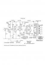
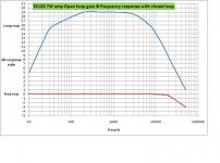
I listen to my version of the ECL82 Junk box amp alot.....7W. Study the graphs. I also had too much gain for line amp apps so I completely butchered the phasesplitter into a concertina using an ECC88 with both sections paralled and simply left the ECL82 triode sections redundant, requiring re math the global nfb loop values. I could have used the ECL82 triode sections but took the decision that the wiring would be too close to the o/p circuit which was asking for trouble so I used a surplus 12GN7 from the junk box for the front end.....there are better tubes for this purpose and less microphonic.
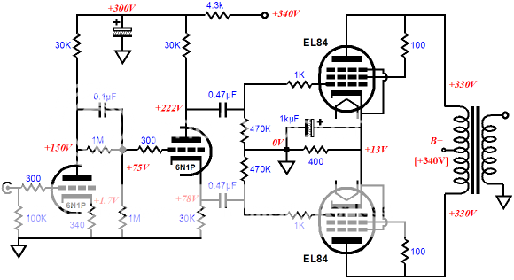
Sowter has an o/p transformer for this amp. Despite it's low power, it has a very clean spectrum and quality of my 150W lumps. The output stage is optimised with each tube taking 31mA quiescent. The entire heater line is lifted to suit the ECC88.
Note o/p stage snubbers, and these are required.
Even though the ECL82 tube was in 1960's small B/W sets as a sweeper, I "never did get on" with the triode section, falling between an 82/83 the mu didn't behave right as a concertina so I scrapped the section.
Those examining the spectrum sidebands will notice the psu ripple is exceedingly low around -92dB down fundamental 7W.....a stabilised 270V psu and the distortion is considerably less than the Mullard version.
richy
Attachments
-
 ECL82 7W schema.jpg46.7 KB · Views: 376
 -
 ECL82 sq 1Khz 7W 4ohms.jpg71.4 KB · Views: 355
 -
 ECL82 sq 10Khz 7W 4 ohms.jpg77.7 KB · Views: 330
 -
 thd vs.Pout graph 1Khz reduc.jpg50.5 KB · Views: 308
 -
 7W spectrum pout.gif24 KB · Views: 305
 -
 loop gain vs.freq res.JPG67.3 KB · Views: 121
 -
 joint over_under.jpg142.4 KB · Views: 180
Sorry guys, I haven't been able to get back at this..... and will probably be another few days.
The plan is to do the checks mentioned above, just to make sure I don't have some silly mistake.....
but if I can't get it resolved, I probably will go to richwalters sch - many thanks for that BTW, really appreciate it. There are few enough designs out there using that valve. The other thing I was thinking of doing was to use a 12AT7 as a phase splitter first, and then use the triode part of the ecl82 for gain.... Or, probably better, I have some 6N1P here that I could use instead of the 12AX7 - gain of 35 seems much more appropriate than the 100 of the 12AX7.
Can someone help me with the resistor changes if I were to sub in the 6N1P? Its really only the plate load resistor that I'd have to change isn;t it? I see a lot of schematics using 47K plate + 1K cathode...... Current b+ to the 12AX7 is ~160V, and can easily tap earlier in the PS for 200-250V...
Fran
Fran
Last edited:
OK, so I went back and found a wiring mistake..... I had 2 of the wires in the OPT the wrong way around. So that fixed, and no other faults found, I powered up..... and now I have a different issue!!
Its motorboating (and squelching a little too). So having read up a little, this seems to be down to high gain in combination with the feedback. Need to do a little more research on cures next....
Now I see why trobbins - you were asking to disconnect the feedback - that's one of the sources of the oscillation, right?
Fran
It is best to simplify all the interactions that interplay in an amplifier when starting to faultfind where a problem is. This would include disconnecting any feedback paths (whether global from speaker, or between stages).
I wouldn't be pointing fingers at a particular concern until you've done a few basic tests, such as looking at waveforms as they go through the amp, and identifying when clipping occurs, and whether lipping of certain stages occurs at the time you hear squelching or motoboating.
Ciao, Tim
I wouldn't be pointing fingers at a particular concern until you've done a few basic tests, such as looking at waveforms as they go through the amp, and identifying when clipping occurs, and whether lipping of certain stages occurs at the time you hear squelching or motoboating.
Ciao, Tim
Will do trobbins. I understand that its best to approach the problem without prejudice.....
I'll do some more work tonight hopefully on it and report back.....
Fran
I'll do some more work tonight hopefully on it and report back.....
Fran
Well guys,
after spending hours and hours on this thing I couldn't get it sorted out. I gave up and used everything to build this instead:
More info here (scroll down a bit) tubecad linky
I used the original iron, so the OPTs are 9K - a little high maybe, and just tied off and insulated the UL taps.
Its sounds fantastic, absolutely beautiful sound with my sachiko horns. There is still a little hum, but not noticeable a few feet from the horns. The original circuit used an EZ81 for rectification, and I swapped that out and used that socket for the second 6N1P, using SS rectification instead. I just used some 1N4007 I had to hand, but I have some schottkys that I can use. The schottkys are 200V rating, but I think by using a few in series I can keep them under the rating - must check that.
FWIW, the heaters are all AC and are running a little hot, ~6.6V, I might also look at adding a dropping resistor to those maybe. Using a choke + cap on the heaters dropped the hum a lot, so my hunch (could be wrong of course) is that dropping the votlage back down a little might drop the hum too.
Anyway, I was really surprised how good this thing sounds. Easily as nice as the F5.
Fran
Hi Fran,
Are you operating the heaters through a humdinger pot to an elevated filtered DC voltage?
I've just getting to the end of checking out my 1960 stereo 7W amp - I'm still using the original 6BM8's, and the common cathode is up to 750R to get idle power down to 6W a tube running a 320V B+.
Richy's results are super - although I am surprised he's running 40% UL taps and not 20% (junkbox availability?). My harmonics are much higher using one of the 6BM8's triode as input gain with direct dc coupling to the other triode as concertina/cathodyne PI, when about 300mV input for 6-7W output. But my amp is a restoration, so I'm not intending to do any major surgery.
Ciao, Tim
There are 2 separate heaters windings used. One is a straightforward 6.3V - originally for the EZ81. The other is a 3.15-0-3.15.
I have a humbucker on the non-CT heater, and the CT of the other going to 1/4 of the B+. I also added in a LC filter on each to chassis. Inductor in series with each leg, with 0.01uF caps across the legs and the centre point going to chassis. copied it out of morgan jones and certainly it dropped the hum a lot.
The hum doesn't change with source or shorted inputs, nor with volume. The LC filter above dropped it a lot... but I was only using some small inductors from old SMPS computer supplies. Its likely the inductance is very low - but I wanted a decent wire size.
My B+ is a little higher than the sch above, about 370V, but the rest of the votlages are pretty much exactly as shown. I tweaked the plate load on the input 6N1 to 24k to get 150V exactly.
Fran
Changing the preset humdinger to a pot for the heater to input stage, and then tuning pot can often achieve a noticeable/measurable hum reduction.
I must admit I'm not exactly sure I appreciate what you are refering to with the LC filters and the connection to chassis. I have MJ's Ed.3 which makes reference to common-mode filtering to chassis (circa Fig. 5.34). However mains hum per se shouldn't be an issue if you are using star-point grounding for your B+ and for the heater CT references and the 1/4 B+ is very well filtered (you can always drop another RC filter from the 1/4 B+ if the 1/4B+ is used for other purposes. It sounds like you may have chassis ground loops present?
I wouldn't worry about trimming heater to exactly 6V3 if it is within 5% - I'm pretty sure you will detect no difference, and any other heater related issues would be insignificant, unless you know that 6V6 comes with a very low mains voltage at the time of measurement.
Yeah - its fig 5.34.
I have used star earth, plus the 1/4 B+ is taken from the last cap (CRCRC - 120uF-56R-120uF-3k3-120uF) with a 200k-100k divider.
It is possible that there are chassis loops, although ground is separated from mains earth via a pair of back to back diodes, paralleled with 15R and 0.01uF cap.
Do you think its worthwhile adding another RC and moving the 1/4B+ to that? Or even upping the uF in the PS?
Fran
Ooooooh yes - across the bias voltage being used for the heater elevation. Hope that helps a lot 🙂
But trobbins words like silent raindrops fell
And echoed in the wells of silence
🙂🙂🙂🙂
big thanks I owe ya a pint!
- Status
- Not open for further replies.
- Home
- Amplifiers
- Tubes / Valves
- Mullard 404? ECL82 amp