Guys,
We're also discussing this tube on this http://www.diyaudio.com/forums/tubes-valves/184488-what-kind-tube-did-i-use-back-then.html forum.
I'm curious to know how this design sounds if any body knows.
We're also discussing this tube on this http://www.diyaudio.com/forums/tubes-valves/184488-what-kind-tube-did-i-use-back-then.html forum.
I'm curious to know how this design sounds if any body knows.
I feel I should be posting this in 2 threads! Anyway, I am planning on restoring this littlelittle mullard amp - I have pretty much all the components needed. A few of the parts will have to be slightly different from the schematic - mainly the caps in the cathode bypass will be much higher capacitance and the pf caps in the compensation circuit at the anode of the 12ax7 will be slightly off from the specced values.
Can anyone tell me would this hugely degrade the sound?
Can anyone tell me would this hugely degrade the sound?
So most of the chassis work is done.... I decided to go a bit retro and I used an upside down roasting pan for the chassis..... and I think it might actually look OK!!!
It'll give me good room on the inside if nothing else....
Fran
It'll give me good room on the inside if nothing else....
Fran
The rebuild progresses nicely!!
I got the PS sorted tonight, and wired the heaters etc. Onwards to the circuit next!!
Fran
I got the PS sorted tonight, and wired the heaters etc. Onwards to the circuit next!!
Fran
Need a little bit of help please!!
In the original circuit, the input goes to the 12ax7 grid via a series of pots for balance, tone and volume. I plan on using mine with a passive pre (well, I'll try it anyway), so I'm building it as a power amp only, input directly to the grid.
I was wondering should I add a grid stopper in there? There is a RC circuit on the plate of the 12ax7 + in series to the second stage to limit HF and LF oscillation.
Fran
Attachments
Last edited:
I guess your simple options are to put ferrite beads, a lowish grid stopper, and a ~30pF grid-anode cap as means to alleviate the impact of extraneous or overdrive input levels. Apart from grid leak, a socket shorting input can be useful.
Shorting would have been very useful - I might just go back and add that.
I have some new 300r carbon comp here that I think I'll press into service....
Thanks for the help.
Fran
I have some new 300r carbon comp here that I think I'll press into service....
Thanks for the help.
Fran
Grrr.....
I have some issues....... hum is one of them, but also something I haven't encountered before in a build.... I have a fairly high pitched buzz, not 50/100 hz stuff, this is a good bit higher. Its similar to what you get from a noisy fluorescent tube.... I know this 'cos I have some of them. I turned off the fluorescents in the workshop in case they were the problem.
My voltages more or less check out, I have about 30V too much at each supply point and to the plates of each valve... but they are all consistently high eg. if the sch says I should have 130V at the plate of the 12ax7, I have ~160, etc etc.
The only difference from the schematic is that it shows a 2M pot with balance and tone controls following it, I dispensed with that and went direct from the input jack to the grid of the 12ax7 with a 1K grid stopper.
As I type this I wonder if its simply a problem of too much gain.... 120mV for full output.
Fran
Can you point to a schematic link, and summarise what you have in place that is different? Usually need to put in audioshort circuits starting close to the output stage and then move back to identify where the problem starts. And also disconnect any feedback paths.
Ciao, Tim
Ciao, Tim
Grrr.....
The only difference from the schematic is that it shows a 2M pot with balance and tone controls following it, I dispensed with that and went direct from the input jack to the grid of the 12ax7 with a 1K grid stopper.
As I type this I wonder if its simply a problem of too much gain.... 120mV for full output.
Fran
Did you put a highish value resistor (470k+) from the grid to ground? If not, the poor 12ax7 will likely be fully turned on and this may be where your noise is coming from.
Gary
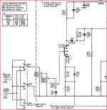
This is the sch - mine is pretty much exactly stock except for:
1. No pots at the input, instead replaced by 1k grid stoppers right at the pins, 330K between input and ground at the RCA jack.
2. Feedback is 680pF//6.2k (for 8R) although the output tx is actaully wired for 4R
3. The coupling caps (C3, C10, C11) are all 0.68uF
4. Cathode bypass caps are all larger, typically 100uF
5. Power circuit: EZ81>>89R>>50uF>>5k>>50uF>>5K>>20uF>>15K>>20uF, these values are very close to whats recommended for a shared supply in the mullard handbook linked back up the thread. They said 5.6K instead of 5K, and 16uF insstead of 20uF.
6. All my voltages are pretty much 30V above whats in the mullard book, but are consistently so across all valves and match up.
I noticed when taking measurements etc, that if I probe about with the DMM probe in around R15, R16 and C10/C11 that the hum and noise changes a bit.
Fran
The thing is, that the amp actually sounds pretty OK!! So I would like to sort it out...
Meant to say thanks for the help so far!!
Also, I'm still wondering if this is not a gain issue.....
Fran
Also, I'm still wondering if this is not a gain issue.....
Fran
Do you have a separate heater winding for the 12AX7? Is it connected to 0V somehow?
Best to generate a capacitor filtered ~50V DC bias supply and connect to wiper of humdinger pot (~100R to 500R) - eg. a 47k/150k divider off the 12AX7 HT rail, with a 63V electro cap filter.
Ciao, Tim
Best to generate a capacitor filtered ~50V DC bias supply and connect to wiper of humdinger pot (~100R to 500R) - eg. a 47k/150k divider off the 12AX7 HT rail, with a 63V electro cap filter.
Ciao, Tim
It's ac heaters all the way. There's a single winding for the ez81 heater, and then a second 3.15-0-3.15 winding for all the ecl82 amd the 12ax7. Pins 4 &5 tied together on the 12ax7, with pin 9 used. Each pp pair wired with heaters in phase for hum cancellation in the tx
Fran
Fran
Oops, meant to say thst the ct of the heater winding is tied to star ground. Ground point is the neg terminal of the first filter cap.
I'll disconnect the feedback tonight....
I'll disconnect the feedback tonight....
It's ac heaters all the way. There's a single winding for the ez81 heater, and then a second 3.15-0-3.15 winding for all the ecl82 amd the 12ax7. Pins 4 &5 tied together on the 12ax7, with pin 9 used. Each pp pair wired with heaters in phase for hum cancellation in the tx
Fran
Fran
Also, I'm still wondering if this is not a gain issue.....
The 12ax7 may no longer be needed as its function might only be to offset the attenuation caused by the tone controls that you no longer need.
Last edited:
Yes, the gain is probably too much alright..... the 12AX7 is used as gain, with the triode part of the ecl82 as phase splitter.
Fran
Fran
Ok, I went back and tried a lot of stuff tonight.
Disconnecting the feedback was no go - simply got oscillation.
I found that by moving some wires about a bit, I could lessen the hum a lot. So acting on a hunch, I added 33k in series with the input, with a shunt of 330k to ground. This cut down a lot of the higher freq noise. Furhter tigthening up of physical layout quietened things down more.
However, that was all with the relatively insensitive speakers in the workshop. With the horns inside, the hum was savage!! The other thing was that its very obvious that the gain is absolutely sky high. My DAC is tuned for 1V output, with a DCB1 buffer, I could hardly let it rise past 9 oclock. So waaaay too much.
The fact that minor rearrangement of wires still indicates to me that what is going on is that the gain is so high, that various parts are acting as antenna for all sorts of noise. Until that gain comes down, there's no way I could practically use this amp.
So, i;m going off to study some of the options out there. Rearrangement of the circuit to use lower gain tubes etc etc all seem a decent way to go.
suggestions gratefully accepted.
Fran
- Status
- Not open for further replies.
- Home
- Amplifiers
- Tubes / Valves
- Mullard 404? ECL82 amp