This amp simply power cycles approximately every 6 seconds. The LED near the RCA labeled 'Shorted' flashes for ~3 seconds every ~6 seconds. When the LED is off, the amp in essence 'charges' itself and produces ~24vDC at the rails, but after ~3 seconds the shorted LED powers up and the rail voltage drops.
None of the power (1F27SP) or output (IRF540) transistors are shorted. I went ahead an pulled all eight IRF540s off the PCB and the power cycling still occurs.
I was able to measure the TL494. These readings were taken in-between the power-cycling while the shorted LED is mainly not lit, unless I used a '~'.
Pin 1: 2.300
Pin 2: 2.2 ~ 4.7
Pin 3: 3.450
Pin 4: 0.865 ~ 4.7
Pin 5: 1.513
Pin 6: 3.178
Pin 7: 0.016
Pin 8: 13.62
Pin 9: ~0 ~ 0.075
Pin 10: ~0 ~ 0.075
Pin 11: 13.62
Pin 12: 13.68
Pin 13: 4.97
Pin 14: 4.97
Pin 15: 4.97
Pin 16: ~0 ~ 0.075
Sure. I just checked the opAmps on the 'top' board and they all get +-19vDC during the 'cycle'. Also the LM339s are getting 13vDC on pin 3

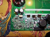
TL494 is most-left:

Half the outputs

I'm calling this the obnoxious LED board. 5 opAmps.

TL494 is most-left:
Half the outputs
I'm calling this the obnoxious LED board. 5 opAmps.
Nothing changed at all. So far all the transistors I've poked at are measuring up well.Did anything change when you removed the outputs?
I let it power cycle for ~15 mnutes hoping it would make something get warm enough to start following the trail. The power supply fets get just slightly warm but nothing could get this adventure started. I'm thinking if I ground the TL494 pin 16 then it should stay on? This amp was almost tossed before I got so it could be an experiment.
Last edited:
Can you take some photos with your good camera (Kodak?) of the area around the LM339s? Email them to me at full resolution. Set the camera to the highest resolution possible.
babin_perry@yahoo.com
babin_perry@yahoo.com
Hey I'm back to working on this little MTX amp. I'm kind of lost with it to tell you the truth and had it aside for a little while.
It would help quite a bit if I could read the numbers on the resistors. Try setting the camera to macro mode. You probably won't be able to capture the area all in one photo so take 3-4 photos to cover this area and email them to me.
babin_perry@yahoo.com
babin_perry@yahoo.com
Perry, I just figured out how to use my camera a little better. I set it to macro, then auto-focus. Then pulling the camera back from the target after auto-focus completes gives me the best results.
I've emailed you a zip archive containing 4 high-res images of the area in question. Thank you very much for having a look at this with me.
I've emailed you a zip archive containing 4 high-res images of the area in question. Thank you very much for having a look at this with me.
Lift Q102. This should disable the protection circuits so clamp all heatsink mounted components and watch for problems carefully.
I pulled Q102 and the amp seems to be partially staying powered on. The Protection LED still flashes every 6 seconds, but the rail voltage is now staying at +-24vDC.
I had previously pulled off the output transistors which were all IRF540. I'll put them back on while I poke and test around other things as well like opAmps and comparators. Nothing is getting hot.
I had previously pulled off the output transistors which were all IRF540. I'll put them back on while I poke and test around other things as well like opAmps and comparators. Nothing is getting hot.
I put the output transistors back in.
The opamps are all getting +-19vDC, and the output pins have no DC with clean audio via RCA input. The gain controls are working and are able to deflect a ~20v sine wave signal on the scope - clean signal
The speaker terminal outputs have barely a wave of signal on them. Its like +-.05v sine wave with the gain all the way up on the amp. and .3v input from the frequency generator. normally that would blow test speakers.
I've traced the opAmp outputs for each channel to various areas of the amp. The signal is strong to the first few components but then it becomes more difficult to tell whats causing the problem.
All 4 channels are having this issue so there must be something up-stream causing these symptoms.
Last edited:
Ive confirmed the output transistors have +-23.5v. Its steady.
One thing though, on the speaker terminal outputs - Every ~6 seconds my scope trace jumps to what appear to be some kind of square wave; but its so quick its like a static electric spark.
One thing though, on the speaker terminal outputs - Every ~6 seconds my scope trace jumps to what appear to be some kind of square wave; but its so quick its like a static electric spark.
I'll take another look at the photos but it will be a couple of hours before I get a chance to do it.
Do the output pins (1, 2, 13, 14) of either of the 339s have pulses that coincide with the pulses on the outputs?
Yes they do switch. Here is what they read. About every ~3 seconds the voltage <Switches>.
U102
Pin 1: 12.67 <Switches> 11.41
Pin 2: 4.95 <Switches> 0
Pin 13: 1.10 <Switches> 4.95
Pin 14: 1.10 <Switches> 4.95
U299:
Pin 1: 0.304
Pin 2: 1.800 (On the scope this pin is showing a very slow 2v square wave)
Pin 13: 0.055 <Switches> 12.50
Pin 14: 0.672
U102
Pin 1: 12.67 <Switches> 11.41
Pin 2: 4.95 <Switches> 0
Pin 13: 1.10 <Switches> 4.95
Pin 14: 1.10 <Switches> 4.95
U299:
Pin 1: 0.304
Pin 2: 1.800 (On the scope this pin is showing a very slow 2v square wave)
Pin 13: 0.055 <Switches> 12.50
Pin 14: 0.672
I've got this amp back up on the bench. Same symptoms; with Q102 removed the rail voltage is +-24vDC and the protection LED flashes on-off-on about every 5 seconds. No audio is getting to the speaker terminals.
The pre-amp board is working as I had previsouly swaped it with another MTX amp and it worked as expected with the other amp. All opamps are getting +- 19.5vDC, and there is no significant DC on any output pins. There are 3 opAmps near the RCA terminals, and each of those are recieving proper voltage and producing proper outputs. None of the output transistors are shorted. All of the electrolytic caps are measuring OK (on the PCB). None of the medium sized surface mount transistors are shorted.
This amp is tricky..
- Status
- Not open for further replies.
- Home
- General Interest
- Car Audio
- MTX Thunder Elite 404