Thanks for the photo Perry.
No outputs came in this amp, could a 30NQ15T be correct?
I never worked on a MTX before, but I think I know how the basics of the output section works looking to the components.
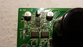
FOD3120 were blown, as well as the NE5332 op-amps.
I changed the NE5532 and I did not yet install new FOD3120 optocouplers (first check if the drive signal is OK).
Both NE5532 heat up pretty good.
Input signal of the FOD1320 is not a nice wave and it's constantly but slowly changing waveform and frequency.
No outputs came in this amp, could a 30NQ15T be correct?
I never worked on a MTX before, but I think I know how the basics of the output section works looking to the components.
FOD3120 were blown, as well as the NE5332 op-amps.
I changed the NE5532 and I did not yet install new FOD3120 optocouplers (first check if the drive signal is OK).
Both NE5532 heat up pretty good.
Input signal of the FOD1320 is not a nice wave and it's constantly but slowly changing waveform and frequency.
Last edited:
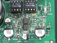
FOD3120 still removed.
It reads 26.9ohm between both FOD3120 vias Pin2 and Pin3.
Also, between FOD3120 (1) Pin 2 and FOD3120 (2) Pin3 it reads 0ohm
Between FOD3120 (1) Pin3 and FOD3120 (2) Pin2 it reads 0hm
Is this nornal?
It reads 26.9ohm between both FOD3120 vias Pin2 and Pin3.
Also, between FOD3120 (1) Pin 2 and FOD3120 (2) Pin3 it reads 0ohm
Between FOD3120 (1) Pin3 and FOD3120 (2) Pin2 it reads 0hm
Is this nornal?
It´s weird that 5532 which are analog, not part of the Class D amp proper, overheat.
Check voltage at pins 4 and 8, maybe you have a regulator or power supply failure and they are getting way more than +/-15V?
Check voltage at pins 4 and 8, maybe you have a regulator or power supply failure and they are getting way more than +/-15V?

As stated above, the regulated power supply is likely damaged.
The 5532 nearest the optocouplers runs hot. The other does not.
For pins 1-4 of the 3120s, the only terminals used are 2 and 3.
What's the rated voltage of the rail caps in that amp?
The 5532 nearest the optocouplers runs hot. The other does not.
For pins 1-4 of the 3120s, the only terminals used are 2 and 3.
What's the rated voltage of the rail caps in that amp?
Last edited:
You were both right, yes.
32 volts between Pin4 and Pin8 of the NE5532 closest to the FOD3120
The other NE5532 has 1.6v across Pin4 and Pin8.
And also, yes, only the NE5332 closest to the FOD3120 heat up the most. But the other heats up as well.
Perry, 100v rail caps
32 volts between Pin4 and Pin8 of the NE5532 closest to the FOD3120
The other NE5532 has 1.6v across Pin4 and Pin8.
And also, yes, only the NE5332 closest to the FOD3120 heat up the most. But the other heats up as well.
Perry, 100v rail caps
Last edited:
±15v is about right for the regulated voltage feeding the op-amps.
You need to measure the pin 5-8 voltage on the 3120s to confirm that their supplies are OK.
I have a part number for the outputs ()IXFH30N50P) in an amp with 160v caps but not for the amps with 100v caps.
You need to measure the pin 5-8 voltage on the 3120s to confirm that their supplies are OK.
I have a part number for the outputs ()IXFH30N50P) in an amp with 160v caps but not for the amps with 100v caps.
The supplies of the FOD3120 read 18.35 and 20.50v. Also too high.
So all voltage supplies of the 4 IC's is faulty.
But what is feeding all 4 IC's? There is a 7805 regulator (5v), there are 2x PHP30nq15T (I assume it's on of those) and a IRF540. I saw in the datasheet the PHP30NQ15T is used for DC-DC converting. So it's probably one of those.
But because this is an N-channel component it must be regulated by a drive wave like a buck converter does (I assume). Couldn't it be a fault in the drive wave of the PHP30NQ15t?
Probing around does not directly conclude which regulator is feeding which IC. When probing around I probe the NE5332 on the 7805 regulator and the PHP30NQ15t on the other side of the board, the 7805 is obviously wrong.
Why do you think the voltages are too high?
What do you think they should be?
What's the circuit board designation for the 5v regulator?
What do you think they should be?
What's the circuit board designation for the 5v regulator?
I was confused with an other component. The correct voltage is 15-30v. So the voltages of the FOD3120 are good.
The board designation is U102
The board designation is U102
This amp I was working on before, from a badge you bought recently I suppose? I check for the outputs. C414 was blown I think...?
Correct Bertje. C414 was not installed in the amp, as well as the output fets.
There is 60V across the pads of C414.
A new cap will fail instantly since the capacitor rating is 25V looking to perry's photo in post #2
Also C413 reads a not stable 27-30v across the pads. It looks like there is a 25v cap installed. Not good I suppose.
Is there anybody with schematics?
There is 60V across the pads of C414.
A new cap will fail instantly since the capacitor rating is 25V looking to perry's photo in post #2
Also C413 reads a not stable 27-30v across the pads. It looks like there is a 25v cap installed. Not good I suppose.
Is there anybody with schematics?
There is 30.2v NE5532's Pin4 and Pin8 close to the optocoupler and 1.6v across the other. Measuring on the oscilloscope measures a kind of unstable sawtooth shape wave on both pins.
NE5532 close to the optocouplers
Pin4: +- -62v (unstable)
Pin8: +- 30v (unstable)
Other NE5532
Pin4: 58v (unstable)
Pin8: 56v (unstable)
NE5532 close to the optocouplers
Pin4: +- -62v (unstable)
Pin8: +- 30v (unstable)
Other NE5532
Pin4: 58v (unstable)
Pin8: 56v (unstable)
Aren't the power supply pins of the two 5532 directly connected?
Aren't the two 10@25v caps the filters for the ±supplies for the 5532s?
Aren't the two 10@25v caps the filters for the ±supplies for the 5532s?
Ok, so, new readings.
The NE5532 PS pins are directly connected. The 25v 10uf caps seems to be the PS caps for the NE5532. They arr connected via a 0ohm fuse resistor. Strange readings from post #16
NE5532 closest to the optocoupler between Pin4 and Pin8 reads 30.45v now
Same reading to the other NE5532.
On the oscilloscope it reads different. Seems like both the multimeter and the oscilloscope can't get a steady DC value. Since the scope sees it as a 2-5v DC due tue the supply being glitchy, I see the multimeter as a better option in this case.
Readings across missing C414 is 58.5v
Across C413 is unstable +-30v
Since this is not a clean DC supply for the multimeter and scope and a kind of sawtooth wave I suppose this means that the regulation are not steady in frequency or duty cycle.
I checked with the oscilloscope, its not steady. Could this be true?
Last edited:
Install a capacitor in place of C414 that can withstand the voltage and re-check its voltage.
Confirm that C413 is within tolerance.
I don't understand:
Across C413 is unstable +-30v
Are you saying that the voltage is swinging above and below ground to a magnitude of 30v each way?
Confirm that C413 is within tolerance.
I don't understand:
Across C413 is unstable +-30v
Are you saying that the voltage is swinging above and below ground to a magnitude of 30v each way?
- Home
- General Interest
- Car Audio
- MTX Thunder 81001 component value/schematics