1:1 is correct.
With a multimeter set to ACV...
Reading from B+ to emitter leg of the driver transistors, I read 6.14v.
Reading from the source leg of the power supply FETs to the gate resistor (side driven by the transformer), I read 6.17v.
These were taken with the B+ voltage set to 10.25v to force the duty cycle to as close to 50% as possible.
With the transformer back in,
I measure 2.28vac B+ to driver emitters
I measure .286vac source to transformer side of gate resistor
Voltage set to 10.25 at B+
So my problem is in front of the transformer.
I measure 2.28vac B+ to driver emitters
I measure .286vac source to transformer side of gate resistor
Voltage set to 10.25 at B+
So my problem is in front of the transformer.
I don't think that meter has the bandwidth. Connect it to your function generator and watch the output of the generator with your scope to confirm that it remains constant. Where does your meter start to drop voltage?
It starts dropping in the 5 k range
With my TPI scope I measure
9.59vac B+ to driver emitter
3.05vac source to transformer side of gate resistor
With my TPI scope I measure
9.59vac B+ to driver emitter
3.05vac source to transformer side of gate resistor
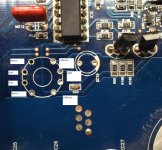
Look at the sony board and compare the transformer layout to the gate and source legs of the PS FETs. Do they have the same terminals of the transformer driving the same points in the circuit as the MTX?
What I find different on the Sony board is the transformer is driven by the driver collectors instead of the emitters, otherwise the transformer pin configuration looks the same where as the outer pins are at ground / source like in the MTX.
Attachments
Are the gate and source for the adjacent pins in the sony for the same FETs?
Reinstall the transformer in the MTX and see if you can find any 1:1 voltage primary to secondary but try all combinations on the secondary windings. I think you'll find the equivalent voltage between the source and the non-adjacent gate.
Reinstall the transformer in the MTX and see if you can find any 1:1 voltage primary to secondary but try all combinations on the secondary windings. I think you'll find the equivalent voltage between the source and the non-adjacent gate.
In the Sony the adjacent pins are not for the same FET like they are in the MTX.
You are correct, measuring across the non, adjacent pins I get the expected 1:1 voltage.
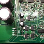
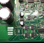
Here are the pictures with corrected labeling.
You are correct, measuring across the non, adjacent pins I get the expected 1:1 voltage.
Here are the pictures with corrected labeling.
Attachments

Did you try hard-wiring it with the terminals crossed to see if it would work?
Bare in mind that the polarity of the two secondary windings may be an issue so if it doesn't work initially, reverse the windings for one of the two secondaries.
Bare in mind that the polarity of the two secondary windings may be an issue so if it doesn't work initially, reverse the windings for one of the two secondaries.
I haven't had the chance yet, but I was thinking swapping the two inside pin locations on the secondary is the fix.
It will probably be couple of days before I can report back on it.
Sorry about the slow pace of progress.
It will probably be couple of days before I can report back on it.
Sorry about the slow pace of progress.
Swapping those two inner secondary pins around seems to have solved the power supply restriction and allows the amp to output it's rated power on a very brief test.
I'll have a bit more time tomorrow morning.
I'll have a bit more time tomorrow morning.
With B+ set at 10.25V I measure 7.32VAC B+ to driver emitter and 7.31VAC Source to transformer side of the gate resistor. The amp is now producing +/- 50.5VDC rail and rises when B+ is increased. The power supply appears to be operating correctly now.
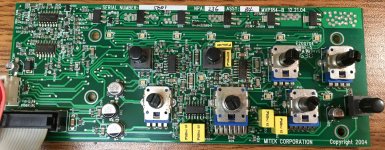
I have run diode check on the LED's to to confirm they all can light up, green, red, and blue. All of the PZTA06/56 check OK in circuit. What do I need to look at to get the colored LED array functioning?
I have run diode check on the LED's to to confirm they all can light up, green, red, and blue. All of the PZTA06/56 check OK in circuit. What do I need to look at to get the colored LED array functioning?
Attachments
At approximately 13.8v in, do you get to ±56v?
Are you getting positive and negative voltage to the two TL074s on the left?
Are you getting positive and negative voltage to the two TL074s on the left?
At approximately 13.8V in, I get ±60v
Yes, here is what I have on all pins
Bottom TL074
1: 1.976
2: 1.976
3: 1.920
4: 14.35
5: .950
6: .692
7: 5.011
8: -9.60
9: .948
10: .948
11: -14.98
12: .009
13: .010
14: .607
Top TL074
1: -11.16
2: 1.125
3: 1.022
4: 14.39
5: 2.503
6: 2.295
7: 11.03
8: 11.05
9: 2.296
10: 3.847
11: -15.00
12: 2.096
13: 2.858
14: -13.73
- Status
- Not open for further replies.
- Home
- General Interest
- Car Audio
- MTX Thunder 5601