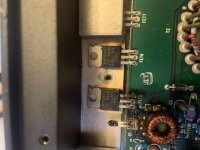
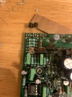
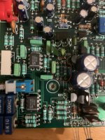
Hi, I have a MTX thunder 2160 that won’t power up. It had burnt power supply fets which I replaced and it had 2 burnt resistors that I couldn’t read the value and the position was burnt off the board but they connect from the small coil To the power supply fets. I replaced them with 1k resistors because the other side of the coil had a 1k but after some research I believe they are supposed to be 61.9 ohm. After replacing a couple other resistors that were bad and a bad cap and power supply mosfets the amp still won’t turn on. I pulled the rectifiers to make sure I don’t damage the output side before putting power to it and there is no power getting to the rails. I also pulled the output fets out too because I have new ones to put in. I believe the IC’s are in protect mode or bad. There is no power coming out of the 494 IC to the power fets. I have 12v at the center leg of the power fets but 0v on the outer legs. If anyone could help with verifying the resistor values of the ones by the small coil and verify if my voltages on my IC’s are ok that would be great. I really appreciate any help, thanks.
TL494
1: 0.01v
2: 4.63v
3: 0.06v
4: 0v
5: 1.57v
6: 3.42v
7: 0v
8: 12.01v
9: 0v
10: 0v
11: 12.01v
12: 12.01v
13: 4.94v
14: 4.94v
15: 4.49v
16: 0v
LMT339
1: 4.73v
2: 0v
3: 12.01v
4: 4.67v
5: 3.38v
6: 1.08v
7: 3.38v
8: 3.93v
9: 4.94v
10: 4.94v
11: 7.17v
12: 0v
13: 4.73v
14: 4.73v
TL494
1: 0.01v
2: 4.63v
3: 0.06v
4: 0v
5: 1.57v
6: 3.42v
7: 0v
8: 12.01v
9: 0v
10: 0v
11: 12.01v
12: 12.01v
13: 4.94v
14: 4.94v
15: 4.49v
16: 0v
LMT339
1: 4.73v
2: 0v
3: 12.01v
4: 4.67v
5: 3.38v
6: 1.08v
7: 3.38v
8: 3.93v
9: 4.94v
10: 4.94v
11: 7.17v
12: 0v
13: 4.73v
14: 4.73v
Attachments
-
 DB33EB4F-E355-424C-918B-C3029D3E39B4.jpg955.3 KB · Views: 241
 -
 974F8F1C-7E75-4CBD-90E7-DE6A1F0227A1.jpg1 MB · Views: 216
 -
 E61FD4E2-7FEE-464E-8DFC-F77F76AAA8E4.jpg981.7 KB · Views: 249
 -
 DF74B798-4D91-4BAC-B296-93BCE1273293.jpg1 MB · Views: 231
 -
 408B576C-3675-4865-B15C-3721AAA89CC2.jpg950.9 KB · Views: 184
Do you have a scope?
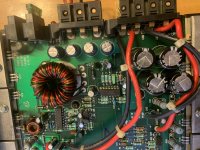
The 'coil' is a driver transformer.
The 61.9 ohm were used in a lot of MTX amps of this size.
Did you check the driver transistors?
The 'coil' is a driver transformer.
The 61.9 ohm were used in a lot of MTX amps of this size.
Did you check the driver transistors?
Hi perry, I was expecting you would be the one to help me. First off thank you for the reply and thank you for your help. I don’t have a proper bench scope but I do have a handheld scope. I only have 68 ohm resistors at hand, will those work instead of the 61.9, right now I have 1k in there. I checked the 4 pnp transistors mounted to the heat sink Q1, Q2, Q30,Q31 and those were good, I also checked Q14, Q16, Q17 and all checked out good. I called mtx and they wouldn’t give me anything not even one single value of a resistor so I appreciate any help I can get. Thanks
Your posts would be easier to read (for me, anyway) if they were broken up instead of one large paragraph.
The 1k may be an issue after the IC is producing drive. 68 would be far better.
Do you see any oscillation on terminals 8 and 11 of the 494 driver IC?
The 1k may be an issue after the IC is producing drive. 68 would be far better.
Do you see any oscillation on terminals 8 and 11 of the 494 driver IC?
Ok, I will put the 68 in instead of the 1k.
I am getting a square wave on pins 8 and 11 of the 494 IC.
I am getting a square wave on pins 8 and 11 of the 494 IC.
I tried editing my posts to break them up For you perry but it wont let me edit for some reason, I am on my Iphone and maybe I need to be on my laptop to edit.
I replaced the 1k with 68ohm resistors. I also found a couple other 10k resistors in the driver circuit that looked like they had been overheated but they tested ok once I pulled them and I went ahead and replaced them since I had some on hand.
I think my voltages on the 494 ic are ok and I should be getting output on pins 9 and 10 but there is nothing and it gets to hot to hold my finger on it down by pins 8, 9, 10, 11. So I think that I am going to order a new one and replace it since I need to order a few other parts for an old ham radio I’m fixing that was passed down to me. But its very possible I am over looking something since I have been doing a lot of research about the ham radio the past few months and I’m going crazy lol.
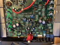
So far everything looks to be in good condition and everything I have tested seems good so I’m not sure where else to check. I will go over the driver circuit again and double check everything. Maybe I missed something.
I replaced the 1k with 68ohm resistors. I also found a couple other 10k resistors in the driver circuit that looked like they had been overheated but they tested ok once I pulled them and I went ahead and replaced them since I had some on hand.
I think my voltages on the 494 ic are ok and I should be getting output on pins 9 and 10 but there is nothing and it gets to hot to hold my finger on it down by pins 8, 9, 10, 11. So I think that I am going to order a new one and replace it since I need to order a few other parts for an old ham radio I’m fixing that was passed down to me. But its very possible I am over looking something since I have been doing a lot of research about the ham radio the past few months and I’m going crazy lol.
So far everything looks to be in good condition and everything I have tested seems good so I’m not sure where else to check. I will go over the driver circuit again and double check everything. Maybe I missed something.
This amp drives the driver transistors with pins 8 and 11, not 9 and 10.
The driver transistors may be shorted.
There isn't enough voltage in the driver circuit to overheat 10k resistors.
As far as I know, there are no 10k resistors in the driver circuit.
The driver transistors may be shorted.
There isn't enough voltage in the driver circuit to overheat 10k resistors.
As far as I know, there are no 10k resistors in the driver circuit.
Thank you perry, I forgot that I had read mtx uses pin 8 and 11.
I pulled all the transistors on the entire board and every one of them tested good.
You are right about the 10k resistors, they are in the protection circuit. I had replaced 2 1k resistors in the driver circuit.
I pulled all the transistors on the entire board and every one of them tested good.
You are right about the 10k resistors, they are in the protection circuit. I had replaced 2 1k resistors in the driver circuit.
So after checking all the transistors and re installing them the power supply is now up and running.
I installed the rectifiers and powered it up and everything stayed nice and cool, the power light comes on and I am getting power to the output fets.
I installed the new output mosfets and tried powering it up with a 5amp fuse in the power line and it power up for a second then blew the fuse. So I installed a 10 amp fuse and tried powering it up and my power supply shut down. I am only using a cpu power supply that says its rated for 14amps at 12v, but when I check it with my multimeter set at 10 amps it trips the circuit in my cpu power supply and shuts off.
So I think my power supply is shutting down because the main rail capacitors are trying to charge up and it pulls more than my cpu power supply can handle and shuts it down. I wish I had a proper bench power supply but this is what I have right now and I only intend to use it for repairing and not to run an amp in my house or anything.
I know there is a chance there is still something wrong with the amp and I am cautious to hook it up in my truck but I think my next step is to hook it up in my truck and see if it will power up and cross my fingers it doesn’t blow lol. I also have a 12v motorcycle battery I could hook up to my power supply and then hook my amp to the battery with a 10amp fuse inline.
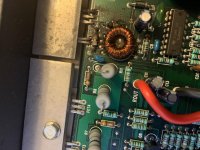
I attached 2 photos with the 1k resistors circled in red.
I installed the rectifiers and powered it up and everything stayed nice and cool, the power light comes on and I am getting power to the output fets.
I installed the new output mosfets and tried powering it up with a 5amp fuse in the power line and it power up for a second then blew the fuse. So I installed a 10 amp fuse and tried powering it up and my power supply shut down. I am only using a cpu power supply that says its rated for 14amps at 12v, but when I check it with my multimeter set at 10 amps it trips the circuit in my cpu power supply and shuts off.
So I think my power supply is shutting down because the main rail capacitors are trying to charge up and it pulls more than my cpu power supply can handle and shuts it down. I wish I had a proper bench power supply but this is what I have right now and I only intend to use it for repairing and not to run an amp in my house or anything.
I know there is a chance there is still something wrong with the amp and I am cautious to hook it up in my truck but I think my next step is to hook it up in my truck and see if it will power up and cross my fingers it doesn’t blow lol. I also have a 12v motorcycle battery I could hook up to my power supply and then hook my amp to the battery with a 10amp fuse inline.
I attached 2 photos with the 1k resistors circled in red.
Attachments
I thought that you were referring to the PS drive. That appears to be for the audio.
How are you checking current of the power supply with your multimeter?
How are you checking current of the power supply with your multimeter?
With the rectifiers out I traced the power supply circuits and I was getting I believe 75 volts in that area of the board on the pnp transistors so I believe the circuit for the power supply drive does go to the 2 opposite corners of the board on the audio side so it’s easy to lose yourself in there while tracing the circuits. That’s also why I pulled all the transistors and tested them.
I am measuring the cpu power supply with my multimeter set to 10amps and was touching positive to positive ground to ground with the amp hooked up but the cpu power supply shuts down as soon as I turn the power on the cpu power supply. And then I made the mistake not thinking about it just hooking up my multimeter to the cpu without the amp hooked up and just touching positive to positive and ground to ground and I essentially was creating a short and that is why it was shutting down when I tried testing it.
A multimeter set to measure current (an ammeter) looks like a short circuit, or just a wire. When you connect your multimeter to the PSU, you are overloading it by presenting it with such a low resistance that it can not provide enough current to maintain its designed output voltage, so the protection circuits kick in and turn it off.
So either my amp has a short between positive and negative and shuts it off. Which my multimeter says there is not a short between positive and ground. Or the amp still has something wrong and the cpu power supply shuts off due to over current. Or the cpu power supply just isn’t up to the task (which I think this is the case). I think my only options are to try to hook it up to my 12v motorcycle battery or or hook it up in my truck. I’m just worried I might blow the fets I just replaced and do more damage. Thanks
The multimeter is designed to be in series with the load when measuring current, not across the load as when measuring voltage.
Some CPU power supplies are sensitive to inrush current.
If you connect it to a battery, install a single, relatively low rated fuse (10-15 amps) in series with the B+ line. Having the semiconductors tightly clamped to the heatsink will reduce the risk of blowing them.
Some CPU power supplies are sensitive to inrush current.
If you connect it to a battery, install a single, relatively low rated fuse (10-15 amps) in series with the B+ line. Having the semiconductors tightly clamped to the heatsink will reduce the risk of blowing them.
So I hooked it up in my truck with a 10amp fuse and no audio hooked up and the fuse blew, I installed a 20 amp fuse since I didn’t have any 15amp fuses and it blew too. I got really unlucky and the 20 amp fuse blew then the piece that broke off inside reconnected it’s self and my power supply mosfets blew. The amp has 2 30watt fuses on the exterior of the amp and for some reason they are fine. Also a side note, I have a amp and sub in my truck already and it has been running good for the last 4 years so there is no problem with my truck.
So I am back in the same boat and have the blown power supply mosfets and 1 out of the same to resistors next to the driver transformer blew.
I had a short between remote and ground so I pulled the power supply mosfets out and the short between ground and remote is gone.
After the power supply mosfets were removed I checked the output mosfets and I have a short between the outer legs on fet’s 1,2,3,4 which are all on one side and the other side of the board they had no short between outer legs. I will pull the ones that show a short and test them out of the amp.
So it’s back to the drawing board to figure out what else is wrong it.
I want to say thank you again Perry for your help and you are a genuinely good man and you’re knowledge is invaluable to the audio community.
The resistors between the driver transistors and the FETs are gate resistors. What value did you install there?
If you go buy fuses, buy 10 and 15 amp ATC fuses that will plug into the holders on the amp. Install only one 10 amp fuse.
If you have an inline current limiter (resistor or incandescent headlamp), use it.
Are you sure that there was a short between remote and ground? There are resistors in the remote circuit that would make that unlikely. You may have had a strand of wire shorting between terminals.
Pull the rectifiers after you think you have the PS repaired. That will isolate the PS from the audio circuit.
First off thank u again Perry. I’ve been away for a while so I haven’t been able to work on it until last night. I got the amp fixed and it is now up and running.
I replaced the power supply fets and the output fets along with one of the gate resistors in the power supply section and it is now working.
It turned out that the IRFZ44’s my friend gave me were fake lol. So the first ones I put in blew and I compared them to the originals and they were clearly fake. Oh well, I ordered new IRFZ44vpbf from digikey and installed them and it powers up and I played music through it.
I have been researching how to set the bias, but I’m not very clear on it so I just set it until the distortion went away. I am worried it is not set correct and was wondering if I could get some help with setting the bias pots.
I turned them fully counter clock wise and powered the amp up. Then I slowly turned it up until the distortion was gone and I repeated the same for the other channel.
I’ve looked at the diagram on Perry’s page but I’m not sure where to attach my probes and not sure what I’m supposed to set it to except to watch for the current to change and that’s it. Thanks
If the bias pot is in the tail of the differential amplifier (common for MTX), you need to confirm that the audio clips symmetrically on the top and bottom of the waveform. Setting it by current draw is typically good but this will confirm. This will need to be done with the FETs clamped down and with a load.
Ok, so I adjust the bias pot while I’m watching the signal for clipping to be equal at the speaker terminal. And do I need to be using a car stereo receiver or will my iPhone with an aux to rca be ok to play the signal into it? Thanks perry
Some amps won't work properly with a signal source that doesn't have a grounded shield (your phone) but you can try it.
I'd adjust it while watching the current and when that's about right, then check the clipping. Be careful not to go too far with the bias to cause excessive current draw.
I'd adjust it while watching the current and when that's about right, then check the clipping. Be careful not to go too far with the bias to cause excessive current draw.
I’m not sure exactly sure where to place my probes so I don’t think I’m doing it right. I’m not sure what readings I’m supposed to get either, I’ve read to many different posts on how to do it and they have confused me.
There are post saying measure at the emitter resistor and other posts saying different places. Am I Making it to complicated in my head and really I just looking at the current on the b+ connection and and when it rises a certain amount it’s good?
Also I have read without the amp powered and measure Milliamps between the emitter resistor and somewhere else that is not clear to me and I am supposed to increase it 1mv?
- Home
- General Interest
- Car Audio
- MTX thunder 2160 repair