A friend asked me to take a look at this amp, apparently he didn't test it before buying it and it has some issues. 
When I got it, the "SHORT" light would illuminate when applying 12v to the remote input (B+ and B- hooked up) and the fans would twitch for a fraction of a second. The power supply did not turn on -> pin 4 of the TL494 was being pulled high.
I checked the output FETs for a short and found nothing.
Seeing no obvious fault I lifted 2 legs of Q101 to bypass the protection circuit, applied power and it came to life.
At this point I started drawing a schematic of the overcurrent protection starting at the shunt bars and checking components as I went. I found Q201 (marked 1G, I'm thinking it's an MMBTA06) to have 39 ohms between the collector and emitter and removed it from the circuit.
Is it safe to power up the amp with this transistor removed? My selection of on-hand spare parts is nearly Zero and I expect to need more parts as I find and correct the other issues.
A few other oddities with this amp:
1.) After lifting Q101 the power supply runs any time there is voltage at the main B+ and B- terminals, it doesn't matter if I have the remote connected or not. Nothing else seems to turn on, only the power supply.
2.) There is currently DC present on the speaker (+) output terminal. This voltage changes depending on the rail voltage. (Rail voltage is dependent on the voltage from my bench PSU.)
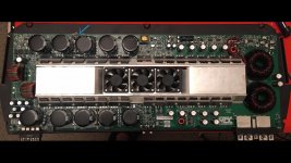
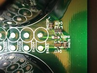
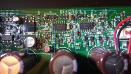
3.) Others have noted a through-hole resistor with silicone in place of 2 surface mount resistors that looks to have been done after initial production. (Link and Link) This amp has the same resistor (blue arrow in overview picture.) I found the short leg broken off. When this resistor is in-circuit there is DC present on the + speaker output terminal. When the resistor is not in-circuit, there is no DC on the speaker terminal. When the power supply is running, this resistor gets warm to hot (hurts to touch.)
4.) Two things you can't see in the pictures (thanks to the 3-layer PCB design) are the connections between the collector Q419 and R201 (pad closer to the LARGE electrolytic cap.) And the connection between R204 (again, pad closer to the LARGE electrolytic cap) and the emitter of Q202.
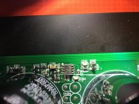
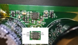
5.) It looks as though someone has been in here before- the solder for one of the large caps was done poorly and there are sections of SMD components that are not sitting square (last picture.)
This is my first large amp and my first MTX amp. As such, I'm working slowly and cautiously.
When I got it, the "SHORT" light would illuminate when applying 12v to the remote input (B+ and B- hooked up) and the fans would twitch for a fraction of a second. The power supply did not turn on -> pin 4 of the TL494 was being pulled high.
I checked the output FETs for a short and found nothing.
Seeing no obvious fault I lifted 2 legs of Q101 to bypass the protection circuit, applied power and it came to life.
At this point I started drawing a schematic of the overcurrent protection starting at the shunt bars and checking components as I went. I found Q201 (marked 1G, I'm thinking it's an MMBTA06) to have 39 ohms between the collector and emitter and removed it from the circuit.
Is it safe to power up the amp with this transistor removed? My selection of on-hand spare parts is nearly Zero and I expect to need more parts as I find and correct the other issues.
A few other oddities with this amp:
1.) After lifting Q101 the power supply runs any time there is voltage at the main B+ and B- terminals, it doesn't matter if I have the remote connected or not. Nothing else seems to turn on, only the power supply.
2.) There is currently DC present on the speaker (+) output terminal. This voltage changes depending on the rail voltage. (Rail voltage is dependent on the voltage from my bench PSU.)
3.) Others have noted a through-hole resistor with silicone in place of 2 surface mount resistors that looks to have been done after initial production. (Link and Link) This amp has the same resistor (blue arrow in overview picture.) I found the short leg broken off. When this resistor is in-circuit there is DC present on the + speaker output terminal. When the resistor is not in-circuit, there is no DC on the speaker terminal. When the power supply is running, this resistor gets warm to hot (hurts to touch.)
4.) Two things you can't see in the pictures (thanks to the 3-layer PCB design) are the connections between the collector Q419 and R201 (pad closer to the LARGE electrolytic cap.) And the connection between R204 (again, pad closer to the LARGE electrolytic cap) and the emitter of Q202.
5.) It looks as though someone has been in here before- the solder for one of the large caps was done poorly and there are sections of SMD components that are not sitting square (last picture.)
This is my first large amp and my first MTX amp. As such, I'm working slowly and cautiously.
Attachments
Last edited:
Removing any part of the protection circuit can be risky. You have to be careful when you initially defeat protection until you're sure that it's not going to cause any damage.
3: What are the circuit board designations for the SMD resistor locations? Searching for those will be easier than having to read every note I have.
4: the connection could be to a supply voltage or ground.
3: What are the circuit board designations for the SMD resistor locations? Searching for those will be easier than having to read every note I have.
4: the connection could be to a supply voltage or ground.
3: R4082 and R4087
The second link is a post of yours if that helps at all.
4: I was just making a note of hidden connections. It's only relevant to the pictures.
The second link is a post of yours if that helps at all.
4: I was just making a note of hidden connections. It's only relevant to the pictures.
Reconnect that through-hole resistor and monitor the DC voltage on the output BEFORE LED 400 is lit.
Use an incandescent lamp if you need to load to output with a load that won't be damaged by the voltage.
Use an incandescent lamp if you need to load to output with a load that won't be damaged by the voltage.
The resistor is connected.
LED 400 never lights up. It's not burned out as it lights up when probed with my meter.
Could it be caused by the protection circuit still being active?
LED 400 never lights up. It's not burned out as it lights up when probed with my meter.
Could it be caused by the protection circuit still being active?
I would like to add:
Unloaded- the fans spin up to I assume full blast.
Loaded- the fans do not come on at all.
Edit, I'll reattach q101 and test
Unloaded- the fans spin up to I assume full blast.
Loaded- the fans do not come on at all.
Edit, I'll reattach q101 and test
With Q101 back in the circuit the amp does not power up. The "SHORT" light illuminates. Same behavior with the speaker terminals loaded and unloaded.
Edit:
I should clarify, any time the remote input has +12v the SHORT light illuminates. This was the case even with Q101 out of circuit.
Edit:
I should clarify, any time the remote input has +12v the SHORT light illuminates. This was the case even with Q101 out of circuit.
Last edited:
Yes I do.
I should clarify, any time the remote input has +12v the SHORT light illuminates. This was the case even with Q101 out of circuit.
I should clarify, any time the remote input has +12v the SHORT light illuminates. This was the case even with Q101 out of circuit.
There is a diagram on the 7801 page that has the control circuit for similar amps. It may be helpful in finding what's shutting down the amp. Do a ctrl-f for:
partial diagram for the control
I'm assuming that you have the 1G transistor out of the circuit.
Regarding the fans, they are both thermally controlled and also controlled by the voltage on the output transistors. They spin up without a load because the voltage is above the minimum threshold.
partial diagram for the control
I'm assuming that you have the 1G transistor out of the circuit.
Regarding the fans, they are both thermally controlled and also controlled by the voltage on the output transistors. They spin up without a load because the voltage is above the minimum threshold.
I will take another look at the 7801 page. I've been referencing that page and the 81000D page while trying to work my way through this one.
That is correct, the 1G transistor (Q201 referenced in my first post) is still out of the circuit.
I know how much you hate it when people make changes like that and fail to update the thread, I won't do that.
I will report back when the protection circuit is sorted.
That is correct, the 1G transistor (Q201 referenced in my first post) is still out of the circuit.
I know how much you hate it when people make changes like that and fail to update the thread, I won't do that.
I will report back when the protection circuit is sorted.
I believe I've found the fault in the protection circuit.
The shorted 1G transistor (Q201) was a red herring, the real problem is the LM311 isn't switching its output. Pin 6 stays at a constant 4.019.
With Q201 in the circuit pin 2 of the LM311 is at 5.56v, with it out of the circuit pin 2 is at 0.001v.
To test I pulled R210 which ties pin 6 to pin 5 (Vcc) and the amp powers up normally. Unlike when the protection circuit was bypassed, the remote has control of the power supply again.
As an aside, I hate finding myself in situations where I can't progress due to a lack of spare parts. I always order extras when I order parts but with so few repairs under my belt that doesn't amount to much. In addition, I'm unsure of what I should realistically have on hand, this is just a hobby for the time being. I vaguely remember seeing a recommendation in the tutorial but I can't seem to find it now that i'm looking for it.
Attachments
The top of the semiconductor datasheets page (SDS in the quick links at the top of the directory) has some. Also search that page for text. There is a text file as well with others. Both give an indication of what they're used in or if they're good generic equivalents. Without knowing what you will be working on it's difficult to know what you should stock.
The following are commonly used.
IRF3205
BD139 and BD140
KSA1220A and KSA2690A
The following are commonly used.
IRF3205
BD139 and BD140
KSA1220A and KSA2690A
Thank you, Perry. I never would have thought to look there. I'll give it another read in the morning and stock up on the lower cost components. With as much as FETs cost, I'm perfectly happy with the leftover spares I have, most of which being 3205's as luck would have it.
You're right, not knowing what my next project is going to be does make it more difficult. It isn't feasible for a hobbyist to be prepared for everything that falls in their lap.
You're right, not knowing what my next project is going to be does make it more difficult. It isn't feasible for a hobbyist to be prepared for everything that falls in their lap.
And again, don't buy from ebay. Only buy from reputable distributors.
Remember that high-current devices need to be matched (date codes) when they're used in parallel.
Remember that high-current devices need to be matched (date codes) when they're used in parallel.
Yes sir! I haven't memorized most of the tutorial yet but both of those tips are on the list of info that I have committed to memory.
Small update-
After replacing Q201 and the faulty LM311 the amp powers up correctly. There's 0.103 V on the (+) speaker terminal with no load attached.
I have not given it an audio signal yet -> The through hole resistor we briefly discussed earlier (replaces SMD parts R4082 and R4087) gets HOT just at idle. Touching it for a fraction of a second is painful.
Why does this resistor dissipate so much heat at idle and should I be concerned? I haven't yet figured out what job it performs. I'm a little concerned it could desolder itself from the board if it gets much hotter.
Look at the voltage across it. I think it's connected between the positive rail and the 18v Zener for the opto-couplers. Calculate the power across it to confirm that it's not above the 2w(?) rating of the resistor.
Resistors can operate at very high temperatures and not be at risk of failing. Check the derating curve for the type of resistor that's being used.
Resistors can operate at very high temperatures and not be at risk of failing. Check the derating curve for the type of resistor that's being used.
- Home
- General Interest
- Car Audio
- MTX TA92001