There could be multiple thermistors.
Are the regulators fed off of the emitters of the two transistors near the diodes you replaced?
Are the regulators fed off of the emitters of the two transistors near the diodes you replaced?
no. they are powered from the transistor emitters on the driver board. I think all the problems are in the power supply + -15v. On tip29 bases tip30 comes 70v, so it should be?
There could be multiple thermistors.
Are the regulators fed off of the emitters of the two transistors near the diodes you replaced?
next to the diodes in the photo tip29c tip30c from the emitters of which there is a voltage on the lm317 lm337
Install a 25v Zener in place of the diodes you replaced. That will make the TIP transistors run hotter and will make the regulators run cooler. It will also help with their reliability since they're only rated for 40v.
15v zener diode will not be enough? Should there be an NPN or PNP transistor in the lm317 power circuit?
The two preregulators are NPN and PNP.
You could install two Zeners in series if you don't have anything near 25v. The regulators need a bit of headroom over the regulated voltage to work properly.
You could install two Zeners in series if you don't have anything near 25v. The regulators need a bit of headroom over the regulated voltage to work properly.
Nothing works. The transistor heats up strongly if the load is lm ***. Am I doing the right thing, before the lm337 is a PnP transistor? to its base a zener diode 22v which makes -22v. Total obtained on the basis of PnP transistor -22v collector -80v emitter -22v
That establishes the fact that the transistors are pre-regulators. I don't know if they are the voltage source for any other components.
If not, use a zener value that causes the heat to be distributed evenly between the regulators and the pre-regulator transistors. The voltage between the input and output of the individual regulators can't be more than 40v. Anything below that is safe.
If not, use a zener value that causes the heat to be distributed evenly between the regulators and the pre-regulator transistors. The voltage between the input and output of the individual regulators can't be more than 40v. Anything below that is safe.
The preregulators are what's rare. Most amps have low voltage windings to supply about 20-25v to the regulators.
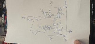
I may be wrong, but here is a diagram of the preliminary stabilizers, I made them at 22 volts. Input 80, Zener diode 22. The minimum zener current is 0.001, the maximum is 0.018, we take the average value of 0.0095. I consider the resistor 58 / 0.018 ~ 6.2kOhm. It turns out that 22 volts with a current of 0.0095 A arrive at the base of the transistor. Seemingly 0.0095 x average h21e tip31 (32) c which I put in, which is about 40, at the output I should have 0.38A (this transistor has 3A max) .0.38x22 = 8.4W at 30 max. Either I'm confusing something, or everything should work. The only thing that confuses me is the high h21e of these transistors .. 50 should be the maximum and the Chinese pribluda shows 200+. Maybe that's the whole problem?
Attachments
The important thing is not to drive too much current through the resistor and diode so they don't overheat. The Zeners are 1/2w. You can use 1w if you want a bit of headroom.
After the voltage at the base is set, only the current that's drawn by the regulators will flow through the TIP transistors.
After the voltage at the base is set, only the current that's drawn by the regulators will flow through the TIP transistors.
I did + -15v. I wound 2 additional windings on transformers. I threw out the transformers, put 2 diodes instead of them, and instead of zener diodes, capacitors 50v 220mkf and cut the tracks from the collectors. As a result, 24v began to come to lm317,337 and everything worked. But another problem appeared, there is a quadratic impulse, there is sound, but the irf640n burns out very quickly ... maybe there are some guesses about what?
I wound 2 additional windings, put 2 diodes and 2 capacitors in front of the lm317,337 and +-15V appeared . All this instead of tip29 tip30 and Zener diodes. lm317, 337 are cold. Now another problem is burn irf640n . I turned it on, checked the pulses on the gates . It seems everything was fine, the amplifier played for 2 minutes and then the hum from the speaker . I checked the meander again and turned it on. Again, the same thing. After 2 failures on 1 shoulder, the meander remained, on 2 direct current . Pre-swing transistors (PZTA42) on the driver Board are intact. There are no burnt resistors . Where to dig I do not know( I do not like that the power in the shoulders is different, can this be due to the fact that the irf640 is not soldered ?
- Home
- General Interest
- Car Audio
- MTX JH1200 repair