Hello, All
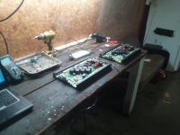
New to the site. Found this place while doing a little research on class D amp repair. Starting a project now with 2 MTX 1501D amps. I have 4 of these monsters but only 1 working right. Its been a few years but I did fix a couple of 502 thunder amps, back in my school days, about this era. Looks to be very similar at first glance.
Looks to be a few guys around here that have quite a bit of knowledge on my model so i thought id join, document my project a bit and hopefully contribute something useful for someone else, and maybe get a couple pointers to help along the way.
The first amp has a capacitor and transistor, (Q263) burned out. Powers up.
The 2nd amp has a transformer burnt, and D326 is burnt. No other apparent signs of damage. Does not power up. That one I was just running test tones to adjust balance with its twin when it went. It was running a 63Hz sine @ 40Vp-p with a 4 Ohm load for about 2-3 min. when it let go.
Any one have any resources, board prints, schematics, O-scope screenshots, notes ect. they would be willing to share I would greatly appreciate it.
Attachments


It's best not to have parallel repairs in a single thread. Let's use this thread for the one with Q263 blown. Start a new thread for the one with the burned output filter inductor.
What do you need to know about the one with Q263 burned?
What do you need to know about the one with Q263 burned?
OK lets focus on amp #1.
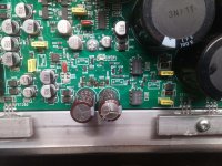
I replaced Q263, R263, D260, and the 35V 1000uF towards the right.
Re-clamped and powered up. Output on the O-Scope tied to output had a few small voltage spikes and returned to near zero, after a couple of seconds LED238 lite up, the power supply whine quieted down and then the 1000uF capacitor blew again. The 2 ICs marked 3120 (Opto couplers?) seemed cool yet along with all the FETs.
Upon another visual inspection there seems to be no other damage.
What is there to know about this area of the amp. Do you know the function of that capacitor?
Thanks for any help.
The area around Q263 and FET260 near the small transformer are the regulator for the opto-coupler near the edge of the board. If the cap is failing, check FET260.
If the voltage on the capacitor (C250?) was high enough to cause it to fail, the opto-coupler has likely been damaged.
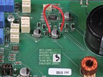
Until you get everything (that you know to be defective) working, I'd suggest jumping the capacitor shown in the attached photo. It will disable the output stage.
If you have a high-voltage capacitor (value not important, 0.1uF or greater, 100v or greater), install it in place of the failing capacitor until you get the regulator repaired.
If the voltage on the capacitor (C250?) was high enough to cause it to fail, the opto-coupler has likely been damaged.
Until you get everything (that you know to be defective) working, I'd suggest jumping the capacitor shown in the attached photo. It will disable the output stage.
If you have a high-voltage capacitor (value not important, 0.1uF or greater, 100v or greater), install it in place of the failing capacitor until you get the regulator repaired.
Attachments
Checked out FET260. The gate and drain leads were very weak and broke when I used solder wick on it. Very low resistance from source to drain, but 28 ohm from source or drain to gate. Cant seem to trigger it off. I installed different FET, 50V capacitor, and different opto coupler.
Upon power up LED238 did not power on, Q263 blew again and there is right at 74VDC across the power supply on U250/ Optocoupler.
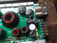
It looks like U250 directly drives FET255-258. These FETs must operate off the "rail voltage" provided by the large toroid transformer and the 8 75339 FETs
Not sure where to go from here. Wonder what that little transformer is there for.
Upon power up LED238 did not power on, Q263 blew again and there is right at 74VDC across the power supply on U250/ Optocoupler.
It looks like U250 directly drives FET255-258. These FETs must operate off the "rail voltage" provided by the large toroid transformer and the 8 75339 FETs
Not sure where to go from here. Wonder what that little transformer is there for.
The small square transformer is for the ±15v preamp supplies and the high-side opto-coupler.
All of the output FETs source their power from the rail voltage.
LED238 won't light up with the jumper on the timing delay capacitor.
A 50v cap won't withstand the full rail voltage that the regulated supply will drive to it when defective.
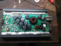
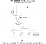
Attached is a schematic for the regulator. All components have to be intact/within tolerance or the regulator will not work.
All of the output FETs source their power from the rail voltage.
LED238 won't light up with the jumper on the timing delay capacitor.
A 50v cap won't withstand the full rail voltage that the regulated supply will drive to it when defective.
Attached is a schematic for the regulator. All components have to be intact/within tolerance or the regulator will not work.
Attachments
Replaced Q264, Q263, D263, D260. Everything seems to check out with the DMM in that area now.
Not sure what D263 does but I had 85 ohm across R264 until i replaced it. Now it measures ~60K Ohm. My working amp reads ~78K Ohm. Maybe on to something here?
I removed FET260 all together. Now i have 50VDC on the opto-coupler power supply. Its a head scratcher yet.
Where do you measure the rail voltage at?
I don`t understand how exactly the regulator circuit is supposed to function yet. I assume the drain on FET260 is tied to + Rail voltage but Im not sure how D260 is controlling this circuit voltage. But I dont think i should have any voltage there with FET260 missing.
I also ordered your repair manual download and have the ISO mounted, but autorun.exe does not seem to do anything. any pointers on that?
Thanks in advance.
Open the index file in the folder with 4 items. To get to the MTX page that I recommended via email, you'll have to navigate to it like you would any other file or use the search function of your computer to find it.
The safest place to measure the rail voltage is at the rectifiers.
In the regulator circuit, the voltage on the gate of the FET is pulled up until the Zener begins to conduct. When the Zener conducts, it turns Q263 on which turns Q264 off and that limits the voltage on the source leg of the FET from going any higher.
Last edited:
That makes sense, I was hoping there was something else controlling power to the optocoupler. If FET260 is out of the picture there should be no power to U250.
I swapped out T471, U450 and still have rail voltage on optocoupler.
I was not sure if that would affect it at all and it did not.
I just pulled the gate resistors and tied the power supply FET gates to ground, without rail voltage there is not voltage on the optocoupler.
Do you have any suggestions on what I should check next?
I'm not sure what you're trying to do. The low-side opto-coupler will have negative rail on pin 5 and negative rail plus 19v on pin 8. Look at the images on the MTX page I sent you the link to.
The main power supply has to be functioning for the low-side opto supply to function.
The main power supply has to be functioning for the low-side opto supply to function.
Well I was trying to figure out how I could possibly have full rail voltage on the Opto supply when FET260 is removed.
I must not have pulled the power supply FETS down right when i had it powered up to test if the opto-couplers sources power from the rail. Now I dont have a power supply and Gate resistor 436 is way out of spec, FETs 436-442 have been sacrificed to the smoke gods now.
Ill have to swap out the power supply FET bank and gate resistor in the morning off my parts rig. Its been a very long day already.
I'm still baffled as to why U250 has such high voltage.
Man would it sure be nice to have a complete schematic from Mitek. Its hard enough working on this stuff when you do know what your working with.
Pin 5 was ok. I had 75VDC across 5-8. according to the datasheet 30VDC MAX. My other amp was running 20VDC.
I found some extra 18V Zeners so I replaced the shunt regulator (D260) again, re-installed FET260. Powered up and my power supply for the optos is back to normal. Everything looks good on the bench now, so time to install in car and test.
My second amp blew the FET just below D326 and R328. You have any info or know what its function is on that circuit? Looks like it took D326 with it again. I think that its a Zener. Ill have to power up my other unit again and see whats going on there. Its soldered to the PCB for a head sink so my head gun is going to have a workout on that one.
Yes 238 is lit.
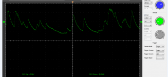
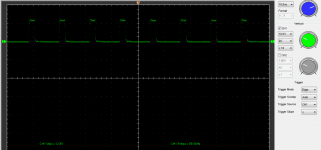
It looks like U201 is supposed to send a modulated square wave to the optocouplers but there is nothing on this amp?
When I first put it back on the bench there was a nice square wave coming into the optocouper set. I was double checking DC power to the couplers when it made a pop sound on the speaker I had connected. LEDs went out due to current surge. I am certain it did not have a slip of the probe? It still has 20VDC on U250, but U240 is running ~17.5VDC now and was right at 20VDC before it popped.
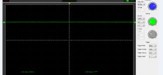
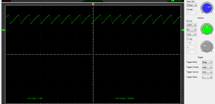
I checked out U450 and FET260 again. Attached screenshots from O-scope.
There is 78VDC across the output terminals now. LED238 stays lit as long as there is no load on the output. Output FETs do not seem to be warming up at all at idle.
It looks like U201 is supposed to send a modulated square wave to the optocouplers but there is nothing on this amp?
When I first put it back on the bench there was a nice square wave coming into the optocouper set. I was double checking DC power to the couplers when it made a pop sound on the speaker I had connected. LEDs went out due to current surge. I am certain it did not have a slip of the probe? It still has 20VDC on U250, but U240 is running ~17.5VDC now and was right at 20VDC before it popped.
I checked out U450 and FET260 again. Attached screenshots from O-scope.
There is 78VDC across the output terminals now. LED238 stays lit as long as there is no load on the output. Output FETs do not seem to be warming up at all at idle.
- Status
- Not open for further replies.
- Home
- General Interest
- Car Audio
- MTX 1501D Amp repair.