I don't know what you mean by plane wave interactions. The drivers are acting in unison like a single larger cone. For how close they are together the interactions are not an issue. The 1/4 wave distance between the drivers will give you the upper characteristic freq where the interaction (or comb interference is an issue). For 7 in spacing that is 480 Hz and above. So for the bass amplification in the TL below 480 Hz, it is not an issue.
I'm not refering ¼ wave between drivers like in an MTM. I'm refering to the ¼ wavelength of the enclosure which is determined by the length.
As for plane waves you should read...
http://www.diyaudio.com/forums/multi-way/100392-beyond-ariel-298.html
That subject was brought up a couple weeks earlier in the same thread, should read through. Good stuff in that thread.
X max is 4mm.
I already have the enclosures made.The measurements you have provided reg partition and port will require cutting the box in half and lots of modifications, which will not be possible with current enclosure. I might as well make new enclosures with better design.
Hi viki,
Yet another option:
b🙂
Attachments
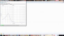
Look at what is happening at ~165Hz, Oy Vie! that second harmonic is out of control.
No,This is only a simulated glitch in your FR interpreting layman eyes/brain.
b🙂
Attachments
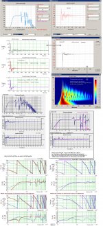
Have you ever adjusted to correct for this? Yes it is a tedious process of back and forth between elements, but can be done. Once done like this the port effecively retains the same aspect ratio and the length/dampening and position of the driver is changed to achieve. The software has been proven to be accurate from 80-200, but has issues with the power response and perhaps acoustic level are flip flopped, dunno, dev is away on business, hopes to correct for this anomaly.
From mathcad comparisons the low end seen at 10Hz should be raised by ~10dB extending to the 80Hz point in the response curve, and above 200 this level is roughly 6dB/octv lower than indicated.
Since I don't have what your running, so cannot make direct comparisons, not working on Win x64 in a vm. Needs to be addressed soon.
And I don't see it as an anomaly. One thing discovered by using this as a reference would yield an enclosure volume close to the Vas of the driver. It can be turned into a deep null or left as a peak in the terminus response, but when this was minimized effectively "nulled" the Vb ~=Vas of the driver. If it is a peak like in your simulations the driver center is off and should be lowered or the top to driver center should be increased to null. If the "ring" at ~165Hz were shaped the opposite then the driver should be raised toward the top of the enclosure or the top chopped.
I encourage you to try this, if for anything other than to further our understanding 🙂
Mike
No,This is only a simulated glitch in your FR interpreting layman eyes/brain.
b🙂
What software is this? It looks like HR but plotted in Holmimpulse, mixed with MJK worksheets?
The image is too small to see in any case...
What software is this? It looks like HR but plotted in Holmimpulse, mixed with MJK worksheets?
The image is too small to see in any case...
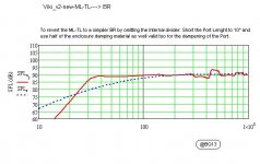
Learn to use the forum tools, see the arrow thing in the corner of the image, it's an overlay, click it to expand. Title bar says Leonard Audio Transmission Line (beta)
http://www.diyaudio.com/forums/software-tools/220421-transmission-line-modelling-software.html
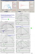
By using my method the driver maintains excursion control by limiting Vb to that of Vas and reduces all even order harmonics.
Example: If you make the enclosure too large the peak @ 2nd in the terminus (that results as the first peak in the driver response) that is to be ignored, causes it to become a null, larger the deeper the null is. If the driver center is offset incorrectly for a given alignment, the peak is shifted one way or the other depending on the phase angle of the node, but remains a peak none the less. It's back and forth repeat at every set to get the correct balance of all to work properly, eg in unison.
Last edited:
Hey Guys, I have been busy with TL Modelling software, See attached Image, See what you can make out of this. I targeted to do a MTM MLTL with design centre at 11" from top, tried creating few sections for varying stuffing,. I some how managed to do some geometries by fluke trying out various differences on resulting Spl.
Kindly check If I have done any good.
Kindly check If I have done any good.
Attachments
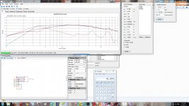
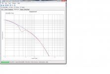
Not a TL but does give you a good representation of what a BR will do 🙂
Watch your excursion limit!
Watch your excursion limit!
Not a TL but does give you a good representation of what a BR will do 🙂
Watch your excursion limit!
Pls Guide me , How do I do it in tl.
Pls Guide me , How do I do it in tl.
I've mentioned what I do to get there, but the standard rules apply to get you started.
Quarter Wavelength Loudspeaker Design
Transmission Line Speakers
Pearls from Martin J King Quarter Wave Design <good tidbits of info here.
Many others I give credit to from websites all around.
Plus alot of reading various threads here and RF theory, those guys had it right back in the 50's! I make antennas too. 🙂
- Status
- Not open for further replies.
- Home
- Loudspeakers
- Multi-Way
- MTMMM Build