I have made a pair of MTMMM Floor standers. used Unibox to calculate enclosure.
I would appreciate if any one can help me optimize these with MLTL technique.
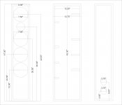
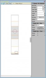
Box Internal Dimensions are-w9" x d12.25 x h45.5
Driver 6.5".
Two 7 cm ports at back located at 3.75" and 8.25" from Bottom , can be modified as necessary.
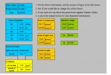
f(s) = 34.32 Hz
Q(ms) = 2.396
V(as) = 21.22 liters (0.750 cubic feet)
n(0) = 0.21 %
M(ms) = 22.84 grams
R(e) = 3.21 Ohms
Q(es) = 0.391
SPL = 85.31 dB SPL 1W/1m
C(ms) = 0.94 mm/N
Piston Diameter = 130 mm
Z(max) = 22.88 Ohms
Q(ts) = 0.336
L(e) = 0.220 mH at 10kHz
SPL = 89.27 dB SPL 2.83 Vrms
BL = 6.36
I would appreciate if any one can help me optimize these with MLTL technique.
Box Internal Dimensions are-w9" x d12.25 x h45.5
Driver 6.5".
Two 7 cm ports at back located at 3.75" and 8.25" from Bottom , can be modified as necessary.
f(s) = 34.32 Hz
Q(ms) = 2.396
V(as) = 21.22 liters (0.750 cubic feet)
n(0) = 0.21 %
M(ms) = 22.84 grams
R(e) = 3.21 Ohms
Q(es) = 0.391
SPL = 85.31 dB SPL 1W/1m
C(ms) = 0.94 mm/N
Piston Diameter = 130 mm
Z(max) = 22.88 Ohms
Q(ts) = 0.336
L(e) = 0.220 mH at 10kHz
SPL = 89.27 dB SPL 2.83 Vrms
BL = 6.36
Attachments
Viki those numbers at a glace look fairly good, 3:1 taper no problem with that (similar to what I have going on with my design).
The issue I do see is that your enclosure picture doesn't show this taper, it's a straight taper MLTL. Additionally would suggest to isolate each driver to prevent plane waves from causing interference with adjoining drivers. Bracing is best if done vertically, split the panels width into thirds (roughly), will lend itself to be the stiffest and raises panel resonance to a point where it doesn't cause issue. Passes the knuckle wrap test, as it is often referred to.
Port placement should be less than 75mm from the bottom. Mine sit around 50mm. Is VERY important, sims show massive gains if this is done, if not at this position can have a negative result. Your ports are a tad on the small size and may cause vent noise if driven hard.
Modeling multiple drivers in a TL is problematic. I've taken the time to model each placement position and never like the result when combined. This complicated the heck out of the design, hence is not built, and months upon months of modeling, testing this or that, to get to where I am today... and I'm still not done.
What driver is this? Don't see an Xmax or power spec, which is helpful to know the drivers limits.
Last edited:
It is a 6.5" mid bass driver, x max is 4mm, power 20 watts.. I am trying to do a 2 way with it, Trying this part for the first time. I have not been able to figure out the drawings.
Any guidance is appreciated
Any guidance is appreciated
What you have is a bass reflex speaker. With the 4 woofers placed as you have them, there is no way you can make the cabinet resonate like a TL. Since there is no electrical time delay between the woofers, they will damp the standing wave in the pipe.
What you have is a bass reflex speaker. With the 4 woofers placed as you have them, there is no way you can make the cabinet resonate like a TL. Since there is no electrical time delay between the woofers, they will damp the standing wave in the pipe.
How do i start doing a Tl.
Need Sd of the driver to continue
Sd -137.7 sq.cm, 6.5" driver, 7" od
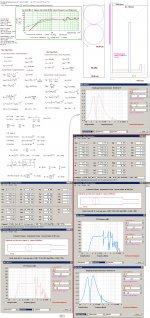
Here is an example using your driver, it's a basic straight line MLTL. Areas adjacient the driver is medium stuffing, next to that are lightly damped. The Base is 1" thick heavy dampening. All defined by default settings. Port is 76mm (3") diameter, 96.5mm (3.8") long and 6.35cm (2.5") from the bottom. Driver center is 54.4cm (21.4") from the top and 76.6cm (30.16") from the bottom. Total internal length ~131cm (51.56") with an internal volume of 22.7 liters. Port velocity peaks at 47Hz @ 7m/s.
Attachments
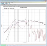
Forgot to add this was at 20 watts single driver.
regarding PM you send I am posting here as I am not able to attach file through that .
I have made a drawing showing the folded 1:10 taper. I have not been able to figure out adjusting driver offset with tl software, also while working with 2 drivers , what will be the design center.
Attachments
You can have 4 drivers and make it work like a MLTL if you go with a bipole configuration (2 front and 2 rear facing in push push) and get the drivers as close together as you can. The median between the drivers needs to be around a third of the way from the top. You can have vents facing front and back, but I like it to be one big down firing one. You can size the initial MLTL volume and vent dimension using a bass reflex program. The assume a length say 45 to 60 in depending on how tall you can make it and calculate the cross sectional area. From this, you have a starting point to tweak with a simulation tool that models MLTL enclosures. However, I have found by accident that if you just use this recipe, it can actually sound pretty good. I did this before I learned how to use AkAbak and got lucky with speakers that sounds good and measured well many times. @Ryani built a speaker with four Tang Band close out drivers and it ended up sounding and simulating well as I learned AkAbak by then. You can find out more about that build here http://www.diyaudio.com/forums/full-range/234535-tangband-w3-881-mltl-build.html
The technique I describe is called the Accidental MLTL (AMLTL) technique and there is a thread that describes it here http://www.diyaudio.com/forums/full-range/231951-accidental-mltl-technique.html
Btw, a bipole with 4 drivers can sound very good and loud even though the two drivers are not pointed at you - you do not have baffle step losses with a bipole and bass extension away from a wall is still deep. In fact, a bipole needs to be far from a back wall to work well. Good luck.
Last edited:
Accidental MLTL is really nothing more than a Bass Reflex with TL characteristics. Using multiple drivers detunes the system, defeating it outright. The port should be tuned to the Fs of the driver to maximally dampen it and the enclosure is @ ¼ wavelength for it to be an MLTL. Neither is happening with the AMLTL as you call it. By extending the response with the port is the same how it's done with a BR system. The result is a much sharper roll off of 12dB/octave instead of the typical 6dB/octave with TL.
I have made a pair of MTMMM Floor standers. used Unibox to calculate enclosure.
I would appreciate if any one can help me optimize these with MLTL technique.
Box Internal Dimensions are-w9" x d12.25 x h45.5
Driver 6.5".
Two 7 cm ports at back located at 3.75" and 8.25" from Bottom , can be modified as necessary.
f(s) = 34.32 Hz
Q(ms) = 2.396
V(as) = 21.22 liters (0.750 cubic feet)
n(0) = 0.21 %
M(ms) = 22.84 grams
R(e) = 3.21 Ohms
Q(es) = 0.391
SPL = 85.31 dB SPL 1W/1m
C(ms) = 0.94 mm/N
Piston Diameter = 130 mm
Z(max) = 22.88 Ohms
Q(ts) = 0.336
L(e) = 0.220 mH at 10kHz
SPL = 89.27 dB SPL 2.83 Vrms
BL = 6.36
Hi viki_v2,
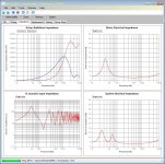
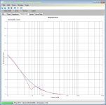
Have a look at this simulation using partly your dimensioning:
b🙂
Attachments
Hi viki_v2,
Have a look at this simulation using partly your dimensioning:
b🙂
Look at what is happening at ~165Hz, Oy Vie! that second harmonic is out of control.
Accidental MLTL is really nothing more than a Bass Reflex with TL characteristics. Using multiple drivers detunes the system, defeating it outright. The port should be tuned to the Fs of the driver to maximally dampen it and the enclosure is @ ¼ wavelength for it to be an MLTL. Neither is happening with the AMLTL as you call it. By extending the response with the port is the same how it's done with a BR system. The result is a much sharper roll off of 12dB/octave instead of the typical 6dB/octave with TL.
Most MLTL's out there are a gradation of BR's and TL's but the MLTL does extend bass response by additional 10 to 15 Hz compared to pure BR, which is the point of a MLTL. The expense is a sharper roll off but multiple drivers can in fact act as one if close together - not detuned at all when I look at response with similar single driver with larger Sd equivalent.
Most MLTL's out there are a gradation of BR's and TL's but the MLTL does extend bass response by additional 10 to 15 Hz compared to pure BR, which is the point of a MLTL. The expense is a sharper roll off but multiple drivers can in fact act as one if close together - not detuned at all when I look at response with similar single driver with larger Sd equivalent.
We have plane wave interaction causing issue if the lines are not isolated, It may measure well, but won't sound as good as it could otherwise. To beat the design, one would want to minimize everything that the original didn't consider.
Yes we can detuned an MLTL to dig deeper, but there is always tradeoffs, higher excursion is one of them, loosing that shallow rolloff and increasing GD are also to be considered, all of which are BR issues. It's no free lunch 😉
Hi viki_v2,
Have a look at this simulation using partly your dimensioning:
b🙂
X max is 4mm.
I already have the enclosures made.The measurements you have provided reg partition and port will require cutting the box in half and lots of modifications, which will not be possible with current enclosure. I might as well make new enclosures with better design.
We have plane wave interaction causing issue if the lines are not isolated, It may measure well, but won't sound as good as it could otherwise. To beat the design, one would want to minimize everything that the original didn't consider.
Yes we can detuned an MLTL to dig deeper, but there is always tradeoffs, higher excursion is one of them, loosing that shallow rolloff and increasing GD are also to be considered, all of which are BR issues. It's no free lunch 😉
I don't know what you mean by plane wave interactions. The drivers are acting in unison like a single larger cone. For how close they are together the interactions are not an issue. The 1/4 wave distance between the drivers will give you the upper characteristic freq where the interaction (or comb interference is an issue). For 7 in spacing that is 480 Hz and above. So for the bass amplification in the TL below 480 Hz, it is not an issue.
- Status
- Not open for further replies.
- Home
- Loudspeakers
- Multi-Way
- MTMMM Build