Hello all, Dean here.
This is a bit of a long one but i wanted to include everything needed to enable some decent feedback
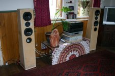
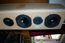
Ive attached some photo's of my latest project.
MTM using the Vifa XT25TG30-04 with 2 x Peerless 6 1/2" 850439
As you can see from the attached photo, everything is in the box (30L Vented) and operating nicely.
I'm currently using a 12dB LR @ 2600Hz for H & L xover which is making some decent sounds.
So whats happening at the moment is exactly the same as everybody else has experienced using these drivers/setup.
1. Shy bass
2. Harsh midband
These are the driver specs as stated by the manufacturer:
Xt25
Nominal impedance [ohm] 4
Voice coil resistance [ohm] 3.0
Nominal power [W] 140
Short term max power [W] 950
Long term max power [W] 400
Operating power [W] 5.3
Sensitivity [dB] 91.5
Frequency range [kHz] 1.5-40
Free air resonance [Hz] 500
Voice coil diameter [mm] 25
Voice coil height [mm] 2.2
Air gap height [mm] 3.2
Voice coil inductance [mH] -
Eff. diaphragm Area [cm²] 5.4
Moving mass [g] 0.30
Magnet weight [g]/[oz] 240/8.5
Force factor [Bl] 2.5
VAS [l] 0.017
Qms 2.50
Qes 0.71
Qts 0.55
850439 x 2 in parallel
Zn 8 ohm
Zmin 7.1 ohm
Zo 40.2 ohm
Re 6.2 ohm
Le 1.3 mH
Cc 9 uF
T-S Parameters
fs 44.9 Hz
Qms 2.28
Qes 0.42
Qts 0.35
Bl 8.9 Tm
Rms 2.34 Kg/s
Mms 18.9 g
Cms 0.66 mm/N
D 13.5 cm
Sd 143 cm2
Vas 18.7 ltrs
Sensitivity (2.83V/1m) -- dB
The plan is to build an XO using these specs so i can enjoy my music collection whilst i learn how to test driver T/S specs and use all this freaking complicated freeware i have downloaded 🙂
The tools i have are:
1 x LCR DMM
1 x Soldering Iron
1 x Excel
1 x Net connection
1 x time/passion 🙂
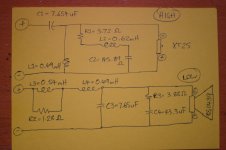
Attached is also a photo of the xo my current calculations/knowledge has come up with.
I guess my questions are:
1. Does anybody know of any links to somebody who has already done all the hard work using these drivers in the same way? Ive read HEAPS of 'kind of' similar stuff
2. Would anybody mind giving me some feedback on the design or even run some sims for me to make sure I'm in the ball park 🙂
3. When using baffle step circuits do i put it before/inline with both the woof/tweeter circuit
4. Is it best to flatten the impedance before or after the xo ??
5. Depending on outcome/listening i plan to add an L-pad to the xt25...
I REALLY appreciate any input on this one guys and apologize in advance if this is a repeat of an existing post.
PS.
1. I'm using only the silver gear on the shelf.. The Alpha 9 needs a replacement mosfet on 1 channel ( if anybody knows of a friendly rep tech near Eltham Melbourne please let me know )
2. The shelves are 22mm MDF with 6mm Ball bearings between them (easy to build and actually works really well )
3. The power leads are home made using leftover cable from work 🙂
This is a bit of a long one but i wanted to include everything needed to enable some decent feedback
Ive attached some photo's of my latest project.
MTM using the Vifa XT25TG30-04 with 2 x Peerless 6 1/2" 850439
As you can see from the attached photo, everything is in the box (30L Vented) and operating nicely.
I'm currently using a 12dB LR @ 2600Hz for H & L xover which is making some decent sounds.
So whats happening at the moment is exactly the same as everybody else has experienced using these drivers/setup.
1. Shy bass
2. Harsh midband
These are the driver specs as stated by the manufacturer:
Xt25
Nominal impedance [ohm] 4
Voice coil resistance [ohm] 3.0
Nominal power [W] 140
Short term max power [W] 950
Long term max power [W] 400
Operating power [W] 5.3
Sensitivity [dB] 91.5
Frequency range [kHz] 1.5-40
Free air resonance [Hz] 500
Voice coil diameter [mm] 25
Voice coil height [mm] 2.2
Air gap height [mm] 3.2
Voice coil inductance [mH] -
Eff. diaphragm Area [cm²] 5.4
Moving mass [g] 0.30
Magnet weight [g]/[oz] 240/8.5
Force factor [Bl] 2.5
VAS [l] 0.017
Qms 2.50
Qes 0.71
Qts 0.55
850439 x 2 in parallel
Zn 8 ohm
Zmin 7.1 ohm
Zo 40.2 ohm
Re 6.2 ohm
Le 1.3 mH
Cc 9 uF
T-S Parameters
fs 44.9 Hz
Qms 2.28
Qes 0.42
Qts 0.35
Bl 8.9 Tm
Rms 2.34 Kg/s
Mms 18.9 g
Cms 0.66 mm/N
D 13.5 cm
Sd 143 cm2
Vas 18.7 ltrs
Sensitivity (2.83V/1m) -- dB
The plan is to build an XO using these specs so i can enjoy my music collection whilst i learn how to test driver T/S specs and use all this freaking complicated freeware i have downloaded 🙂
The tools i have are:
1 x LCR DMM
1 x Soldering Iron
1 x Excel
1 x Net connection
1 x time/passion 🙂
Attached is also a photo of the xo my current calculations/knowledge has come up with.
I guess my questions are:
1. Does anybody know of any links to somebody who has already done all the hard work using these drivers in the same way? Ive read HEAPS of 'kind of' similar stuff
2. Would anybody mind giving me some feedback on the design or even run some sims for me to make sure I'm in the ball park 🙂
3. When using baffle step circuits do i put it before/inline with both the woof/tweeter circuit
4. Is it best to flatten the impedance before or after the xo ??
5. Depending on outcome/listening i plan to add an L-pad to the xt25...
I REALLY appreciate any input on this one guys and apologize in advance if this is a repeat of an existing post.
PS.
1. I'm using only the silver gear on the shelf.. The Alpha 9 needs a replacement mosfet on 1 channel ( if anybody knows of a friendly rep tech near Eltham Melbourne please let me know )
2. The shelves are 22mm MDF with 6mm Ball bearings between them (easy to build and actually works really well )
3. The power leads are home made using leftover cable from work 🙂
Attachments
Additions
Also...
1 . The baffle size is 12" wide
2 . The xo drawing should have 2 x 850439 in parallel
Cheers dean
Also...
1 . The baffle size is 12" wide
2 . The xo drawing should have 2 x 850439 in parallel
Cheers dean
Hey Dean,
Using Boxplot I got vb=25 ltrs, fs=50.6, vent length15.3 cm, vent dia=7.5 cm (3 inchs). That looks like a large diam port in the photos(?), It maybe letting too much midrange through. Thats one possibility. Have you chamfered the inside of the baffle for the woofer holes? This could also cause the midrange to break up. Also, How long is the port? It looks quite short in the pics, it could cause weak bass as well. Is that stuffing inside the box? Stuffing can help the mid breakup (depending on its cause) but can also cause a bass shy sound. Nice looking speaker I gotta say!!! let us know how you get on. Hope this helps mate. cheers mick.
Using Boxplot I got vb=25 ltrs, fs=50.6, vent length15.3 cm, vent dia=7.5 cm (3 inchs). That looks like a large diam port in the photos(?), It maybe letting too much midrange through. Thats one possibility. Have you chamfered the inside of the baffle for the woofer holes? This could also cause the midrange to break up. Also, How long is the port? It looks quite short in the pics, it could cause weak bass as well. Is that stuffing inside the box? Stuffing can help the mid breakup (depending on its cause) but can also cause a bass shy sound. Nice looking speaker I gotta say!!! let us know how you get on. Hope this helps mate. cheers mick.
Ah sorry dean,
Xover I'm pretty sure goes, filter, bsc, zobel. I'm sure I will be corrected if thats wrong. Also pad goes after filter. Your xo has bsc, filter, zobel. I've never tried doing it the other way around so i can't testify how much difference it makes, if any. Cheers, Mick. BTW, is that a notch filter on the tweet? Never made one of them.
Xover I'm pretty sure goes, filter, bsc, zobel. I'm sure I will be corrected if thats wrong. Also pad goes after filter. Your xo has bsc, filter, zobel. I've never tried doing it the other way around so i can't testify how much difference it makes, if any. Cheers, Mick. BTW, is that a notch filter on the tweet? Never made one of them.
Hi Thunk, I saw this yesterday but thought someone more knowlegeable about crossover design than me would speak up, but perhaps not 😉... I think that the RLC on the tweeter is probably a resonant peak filter? I'm not sure what the values normally would be for this but the cap looks very big to me at 145uf (note that you have an ohm symbol on it).
With the woofer I assume the first bit is the Baffle step comp, and that the last bit is the impedance comp (zobel), I'll point to something I wrote a while back when I was experimenting with impedance comp... ---> http://www.diyaudio.com/forums/showpost.php?p=573539&postcount=4 worth doing some experimenting before finalising the design I'd say 🙂
The graph on the peerless looks like it starts to peak starting at around 3.2Khz with the peak at about 4Khz It might pay to consider putting a notch filter in at somewhere around 3.8Khz to tame that peak.
With a 2.6K crossover freq at 12db / octave that peak is going to be well and truely prominent I'd say and may be what you are hearing as harshness, could also be some cone breakup...
Please take all of this with a very large grain of salt, as I have not yet designed my own crossover, and I'm a little rusty on the theory, as it has been about 4 years since I was doing the research!!
Tony.
I think resonant peak filter makes sense Tony, if I remember correctly this tweeter is not the easiest to crossover. I think I recall reading that a lot of diyers had trouble with it, not sure what the answer is, maybe a higher order slope?
Sorry Dean, what I thought was stuffing on closer inspection turns out to be pvc tubing I think.
The reason i ask about the chamfer behind the bass drivers is, I had a very similar problem with the breaking midrange, and worse than expected bass
no amount of xover tweaking could fix! betcha can't guess what the real culprit was?
May not be the problem in your case, but, IME, definately worth a mention especially with thick front baffles.
Mick
Sorry 4 the double post but, I'm assuming that the xover hasn't been built yet? If not;
What were u using for a crossover when you heard these sounds?
I think the answer to this could shed some light on the subject real quick!
What were u using for a crossover when you heard these sounds?
I think the answer to this could shed some light on the subject real quick!
Hey Prickears/Wintermute & Pete.
Ill try and break this down but there's always sooooo many questions!!
Prickears...
1. The box is 28 liters after bracing.
2. The port is 8.3cm (ID) x 15cm. The white part 🙂 IS the plumbing pipe attached to the back of the jaycar angled head and I've been changing the length with varying effect. The bass coming from the port sounds pretty clean with no "noticeable" chuffing or mid range output using the ear too close for my health test
3. I used the same 22mm round over router piece on the inside of the driver mounts as the rounding on the outside of the cab ( one of the joys of using 30mm MFD 🙂)
4. The internal stuffing is 25mm corrugated acoustic foam (painfully expensive from Clark rubber 🙁 ) lined on 3 walls. I have heard about getting great results using mineral wool. Do we know of a supplier in melb and whats a rule of thumb for internal coverage area (eg 25%/50%)
5. The bass was very shy without the current stuffing and really gained allot of depth after stuffing. BUT... I have to crank the system to hear the bass detail. I'm thinking thats the baffle step issue I'm hoping to resolve with L3+R2
6. As far as XO layout, this is were I'm confused. Vance talks about putting his impedance shaping circuits on the amp side to minimize xo load/shift whilst others pages like Elliot Sound swear by filter first..... It seems like i may have to try both and listen for a difference since i cant check the response changes at this point 🙂
7. Yup, that's a series notch filter centered at 550hz (tweeter impedance peak) and is reported to be a very handy little device. Many have stated that if the XO is 12dB and 2 octaves above this peak it may not be necessary whilst others have made it clear that this is THE major factor in cleaning up the midband responce of the xt25... Ill get back to you on that one.
Winter...
8. The variance between 1 design method over another seems to be one of the bedrocks DIY audio is built upon 😛. Without real test equipment i am going to wing it and be prepared for a few late night XO rebuilds 🙂 Ive started using speakerworkshop to see if i am in the ballpark and will keep this thread up to date with any findings
9 . Ive looked at that 4k peak also but my limited understanding assumed that an LCR was only for impedance changes?? So i can use another 1 to tame the responce peak?
10. As you can imagine, with the tweeter peak and woofer peak summing around 3/4k i have got some crazy distortion going on which can get particularly painful on almost all vocal/acoustic material.
Ears/Pete..
11. At the moment all that is being used is a 12db LR XO @ 2600hz for both the high and low pass. I have used an L-pad but removed it after trying different attenuation levels (1/2/3dB) because i was still getting the midband breakup and lost the top end sparkle this tweeter is so good at. This was the action that made me realize I wasn't dealing with only a driver sensitivity issue.
Cheers again guys.. Its great to be getting your input and any new ideas could be the magic that takes this project from decent to amazing.
Also guys, I am currently having all posts reviewed by the moderators which may be causing some time delays and so appreciate your patience...
Dean
Dean
Hi Dean,
quick response, but have a read of the following from David Weem's book specifically the notch filter crossover and associated bits (I have this book and would recommend it as a not too technical intro type book. Dickasons loudspeaker cookbook I also have, and is great but has a much steeper learning curve)
I'm not sure if this type of crossover is appropriate for this driver, but might be worth considering... I guess (but I'm unsure) you could use both a notch filter on the peak and a normal crossover as well.... one thing I definitely don't know is what effects that would have on phase.
On the matter of where to place your impedance compensation, my understanding is that you use impedance comensation so that the impedance presented to the crossover network is as constant as possible, as the filters response is dependent on the resistence of the driver at any given freq. If that resistance is rising as freq rises then your filter becomes less and less effective at the frequencies it matters most, so based on that I think I would lean towards what Rod says 🙂
Tony.
Last edited:
Fantastic Winter...
This book by David is exactly what Im after and more inline with my current skill level.
Ill read up and keep the thread up to date with developments as i go so anybody else using these drivers/setup can take a few shortcuts
Dean
This book by David is exactly what Im after and more inline with my current skill level.
Ill read up and keep the thread up to date with developments as i go so anybody else using these drivers/setup can take a few shortcuts
Dean
By the way were did you buy your copy? Allot of places have it for about $43 aus but are out of stock?
Cheers Dean
Cheers Dean
a couple of things come to mind - both HP & LP sections are 2nd order yet you have the polarity of the tweeter reversed, have you tried it normal polarity?
Try removing the R across the BSC inductor, that should give you full BSC & hence more low end (But you'll probably have to pad down the tweeter a touch to match sensitivity)
Try removing the R across the BSC inductor, that should give you full BSC & hence more low end (But you'll probably have to pad down the tweeter a touch to match sensitivity)
Won't removing R from the bsc simply lower the xo frequency of the lp filter? No, I don't know, I'm genuinley curious!
Dean Thanx for that clarification, I guess we can rule out box tuning problems.
I have Weems book also and it's proved very helpful over the years, but I must acquire some testing equipment to make the cd-rom more useful.
Mick.
Dean Thanx for that clarification, I guess we can rule out box tuning problems.
I have Weems book also and it's proved very helpful over the years, but I must acquire some testing equipment to make the cd-rom more useful.
Mick.
When looking at my BSC calc, as i adjust the dB value by which I want to attenuate the upper frequencies, the value of R and L change.
The calculator was created in Excel using this paper by J.king as the reference and has been checked against online calcs for better or worse.
As far as polarity goes Pete your making allot of sense. Ill try it and report back asap... So the idea being with H&L 12dB filters both drivers are already 180 deg out of phase and should be in phase with each other already?
I originally reversed the tweeters polarity and planed to wire it that way with the new XO after ready Vance's instructions in LSCBv6. Re-reading that section as we speak..
Attachments
I might be the only one but i reckon vance could really use some more diagrams 🙂
I'll do a little exercise and you guys can tell me if what you think...
1st order XO = 90 deg out of phase (so each driver 45 = 90 deg)
2nd order XO = 180 deg (each driver being 90 deg)
etc
From reading LSCB this sort of assumption might be made and seems to be one of a few ways to understand the text...
Have i missed the point?
G'day Dean,
Do you have the ability to leave the xover out of the box for the time being. If you have a bi-wirable input doover its easy enough to do. This will make tweaking ALOT easier. Otherwise you maybe able to wire the bass drivers staight to your input, then exit the tweet wire through your port, crude but effective. That way you could build and try different bsc and zobels and polarities 'on the fly'.
Mick.
Hey Mick..
Yep, got the filter setup externally with a biwire terminal. The xt25 is wired to the top set and the woofers are wired in parallel to the bottom set of posts.
My plan was to actually mount the XO's in external RF shielded boxes when finished for mechanical/electrical isolation.
We both know the tweaking NEVER stops. 😀
Dean,
Re: phase shifts, what you've written is also the way I anderstand it, However how much do corrective circuits shift phase? Does this depend on wheather it's in series or parallel, and how many components each has? Then do you time align drivers based on this, and taking into account fxo?
Tweaking NEVER stops.................. Oh boy, don't I know it!!!😛
- Status
- Not open for further replies.
- Home
- Loudspeakers
- Multi-Way
- MTM - Stage 2 - Finalizing XO before build and need HELP :)