Good point....
Getting into the domain of proper XO sim software here me thinks...
What do u use for xo design, being the easiest/free??
Another question... The Nom Imp of my woofers is 8 ohms but my MMD measures imp as 3.2 at the terminals with 2 in parallel. So when running XO calc do i use 4 or 3.2 ohms???
Getting into the domain of proper XO sim software here me thinks...
What do u use for xo design, being the easiest/free??
Another question... The Nom Imp of my woofers is 8 ohms but my MMD measures imp as 3.2 at the terminals with 2 in parallel. So when running XO calc do i use 4 or 3.2 ohms???
I just generally use the online one on diyaudioandvideo.com, and try to avoid most of these problems by using easy to cross drivers where ever possible.
I've found through years of reading, the grey heads do this and try to stick to first order slopes where ever possible, (less phase shift), the bald guys, try to correct inherent problems by adding more!!!!!! Tweaking proved it to be dead true....IME.
Another bit of advice that helped me no end was "try to avoid crossing over in the midrange". This is where your ear is most effiecient. Mother nature designed it that way to better hear the human voice. Any problem there, is going to be very difficult to mask!
Check thread 'p22wp transmission line' for my design, its still in its infancy, but the clarity through the midrange blew me away instantly, and the drivers were dead cheap.
What your measuring at the terminals is the resistance of the voice coil (RE), (of 1 driver div 2, for series, as you already know) plus your wire resistance.
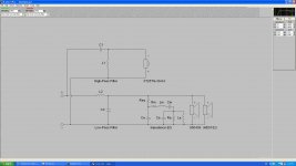
Impedence is different, as it changes with frequency and can be followed on your response graph, it's the impedence curve that you aim to flatten with the zobel. That will (should) hold the impedence close to nominal at your xo point. So, xo to nominal impedence not RE. Your crossover in the pics shows your on the right track there.
What your measuring looks normal to me. Genly rattle your fingers on the cone while you take this measurment, you'll get the idea......
Mick
I've found through years of reading, the grey heads do this and try to stick to first order slopes where ever possible, (less phase shift), the bald guys, try to correct inherent problems by adding more!!!!!! Tweaking proved it to be dead true....IME.
Another bit of advice that helped me no end was "try to avoid crossing over in the midrange". This is where your ear is most effiecient. Mother nature designed it that way to better hear the human voice. Any problem there, is going to be very difficult to mask!
Check thread 'p22wp transmission line' for my design, its still in its infancy, but the clarity through the midrange blew me away instantly, and the drivers were dead cheap.
What your measuring at the terminals is the resistance of the voice coil (RE), (of 1 driver div 2, for series, as you already know) plus your wire resistance.
Impedence is different, as it changes with frequency and can be followed on your response graph, it's the impedence curve that you aim to flatten with the zobel. That will (should) hold the impedence close to nominal at your xo point. So, xo to nominal impedence not RE. Your crossover in the pics shows your on the right track there.
What your measuring looks normal to me. Genly rattle your fingers on the cone while you take this measurment, you'll get the idea......
Mick
By the way were did you buy your copy? Allot of places have it for about $43 aus but are out of stock?
Cheers Dean
I got it at Jaycar years ago, but they don't seem to stock it anymore. On the phase questions, that's one area I need to work on... I don't particularly like math wich makes it all the harder!
Tony.
This will be my first and last post here as I usually don't make this kind of post these days.
Note that what determines the filter order is not an electrical order but an acoustical rolloff order. In this case (or in most cases with this kind of driver combination for home speakers), you want to shoot for Linkwitz-Riley acoustic 4th order. For your particular driver combination, I am 99% sure that this is achieved by using a second order electrical low-pass filter (with or without a Zobel) for the Peerless and a third order electrical high-pass filter for the Vifa XT25. The tweeter should be wired in normal polarity.
- jAy
Last edited:
Thank you Jay.
A appreciate your input but like all Diy'ers am left with the eternal question...
WHY?
Cheers Dean
A appreciate your input but like all Diy'ers am left with the eternal question...
WHY?
Cheers Dean
Hi Dean have a look at the natural rolloff of the woofer, then add in the rolloff that the crossover introduces, when summed you should get your 4th order rolloff. Now I haven't looked at the rollof of the tweeter but I assume it is more shallow hence Jay suggesting third order for it. You might want to do a search on target response 🙂
Thanks Jay for stepping in when the blind are leading the blind 🙂
Tony.
Thanks Jay for stepping in when the blind are leading the blind 🙂
Tony.
Last edited:
Hi Dean, Have a look at the freq response curves for the two drivers. The XT25 drops by around 6DB between 1Khz and 500Hz (one octave) and the peerless drops by around 12db between 3Khz and 6Khz (again one octave and ignoring the peak at around 4Khz) 🙂
Tony.
Tony.
OK... I'm kinda getting this.... Are you saying that the chosen electrical slope should match the drivers acoustic slope in most cases?
This sounds like an interesting idea but not something i have ever heard of doing before?
Will i be dealing with strange phase issues combining odd and even order XO slopes?
I guess that's the thing about XO's, once you buy enough parts you can start trying anything... Hmm maybe i should look at those cheap Russian military caps after all 😀
Cheers again guys, I'm even more confused but ignorance is not audio bliss so on we go
No you want a particular target response (ie slope) If this is 24db/octave and the speaker already rolls off at 12b/octave then you only need 12db/octave on the electrical side 🙂
Both the woofer and the tweeters rolloffs should match each other (ie in this example 24db/octave) in order to sum properly for a flat response 🙂 Since the tweeter rolls off at 6db/octave you need an additional 18db/octave from the electrical side, hence a third order on the tweeter as opposed to 2nd order (12db/octave) on the woofer.
At least this is what I believe Jay was talking about, something I had read (ages ago) and forgotten 🙂
Tony.
Im with you now winter....
Would the electrical and acoustic slopes have to begin and end at the same frequency to sum???
I dont think that's what your saying, but that's what my brain keeps yelling at me 😱
Doing some research and will get report back asap
Would the electrical and acoustic slopes have to begin and end at the same frequency to sum???
I dont think that's what your saying, but that's what my brain keeps yelling at me 😱
Doing some research and will get report back asap
Hi dean, I tried doing a search for some graphs which show the roloffs and summed response and came across this article The first section on phase is well worth reading 🙂 Phase is something that usually does my head in, but this article helped a lot, especially the graph demonstrating the difference in phase.
It is primarily an article about using cad software for designing crossovers which is beyond the scope of what we are discussing, but have a look a bit further down and you will see the combined response of the drivers with the crossover and the summed response as well. So in a way I guess your question is correct, but maybe not how you meant 😉 You do want symetry around your acoustic and electric slopes both meeting a a point to sum correctly, but they don't start at the same frequency, they are idealy a mirror of each other.
If you look at the first example in that article, the crossover freq is 2.5Khz the dotted lines represent the response of the driver + the filter for each of the woofer and tweeter, note that the woofer starts rolling off at around 1.2K, because the tweeter is still providing some sound level even at 1.5K (though admittedly around 20db down) the two sum together to make a relatively flat response (and this goes for all of the frequencies in between)... this is why the phase is so important in the crossover region, if the output is not in phase it won't sum correctly... This is also why it is important for the "actual (ie acoustic + electric) rolloffs to match each other as closely as possible (ie be a mirror of each other). If you look at the tweeter it is starting to roll off around 5K (note each is starting it's rolloff 1 octave below/above the crossover freq).
Hope that helps a bit 🙂
Tony.
Tony,
I have often read '1st order filter, exibiting 3rd order slopes', in crossover descriptions. Is this what they are refering to? The combined accoustic + electrical slope of the drivers + filter?
Mick.
I have often read '1st order filter, exibiting 3rd order slopes', in crossover descriptions. Is this what they are refering to? The combined accoustic + electrical slope of the drivers + filter?
Mick.
Hi Mick, without reading the original I couldn't say, but my guess would be yes 🙂
Remember, I'm not an expert on this, I probably just have a little more knowledge than yourself, all from reading, and a tiny bit from playing/measuring (only 1st order).
Tony.
Remember, I'm not an expert on this, I probably just have a little more knowledge than yourself, all from reading, and a tiny bit from playing/measuring (only 1st order).
Tony.
mtm
Just looked up tymphanys web site and they say that your drivers are discontinued? Must be old stock
I am attempting a similar project that uses the same tweeter and two P830875 nomex drivers in a mtm format to date I haven’t put these together (waiting for the dude at the cnc machine shop to finish my designed boxes) my cabinets are 34 litres rear ported
I hope that I don’t get the same difficulties that you are having with the crossover area
Aim going to use 18db Butterworth filters and see how they workout
I will post some snaps of the project as it unfolds
We keep an eye on your project and see how it pans out
Cheers Speedie
mtms
what are your box dimensions maybe i can run it through bassbox pro and xo software to see how close it is to mine?
what are your box dimensions maybe i can run it through bassbox pro and xo software to see how close it is to mine?
Hi Speedie.
Sorry for the late reply... Work Work Work
The box dimensions are 1250(H)*250(W)*230(D)
All sides using 30mm MDF
As a side note I am looking at ordering Elliot Sounds 24dB Active XO boards (P09) and using both my amps for an active solution...
1. To side step my lack of experience in passive XO design and until I can test my drivers properly.
2. I have run my system using the existing passive XO's with both amps and had some great results so i figure with an active XO i might get closer again to what i know these drivers can achieve .
But, if you feel up to running a few numbers i look forward to your results and input 🙂
Best of luck with your project and drop a link in this thread when you get your thread up and running in case i miss it.
Cheers
Dean
software
hay dean got your post will crunch some numbers for you and see what bass box suggests
seems like this is almost an exclusively aussie post
ps i was looking at the last silicon chip issue and they have some diy active crossover pc boards could be good for you!
hay dean got your post will crunch some numbers for you and see what bass box suggests
seems like this is almost an exclusively aussie post
ps i was looking at the last silicon chip issue and they have some diy active crossover pc boards could be good for you!
Madisound shows that tweeter as having an fs of 500hz.
Is that correct?
If so, you're not doing yourself any favors by crossing that over so high.
There's simply no reason to be higher than 3x fs at the maximum. Which would be 1,500hz.
Secondly, I see a slight peak at 3,000hz. That is THE notorious point of harshness in music to our ears.
Put a notch filter there, and I bet the harshness goes away.
Also, MTM's like lower crossovers for the tweeter. So you should seriously consider redoing that to closer to 1,500hz.
The half wave length right now at crossover frequency, is 2.6".
You would increase that to 4.5" if you took it to 1,500hz.
And that would go a long way to making the speakers sound better outside of the sweet spot.
- Status
- Not open for further replies.
- Home
- Loudspeakers
- Multi-Way
- MTM - Stage 2 - Finalizing XO before build and need HELP :)