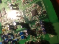
Hey guys, I know there are a lot of threads on this amp, and I have read all of them I
Could. I am having problems getting +vcc to the tl494 to get a square wave. I'm guessing something in ic5002 has the +vcc blocked. All pwr supply and output mosfets are out of the amp. I replaced both voltage regs. I replaced ic5201(battery detect). any thoughts?
Could. I am having problems getting +vcc to the tl494 to get a square wave. I'm guessing something in ic5002 has the +vcc blocked. All pwr supply and output mosfets are out of the amp. I replaced both voltage regs. I replaced ic5201(battery detect). any thoughts?
You need to compare the voltage on the pins of IC5002 with those in the service manual. Do you have VDD (most important)?
1: 4.9.v
2: 4.9v
3: 4.9v
4: 4.9v
5: 4.9v
6: 4.9v
7: 4.9v
8: 4.9v
9: 4.9v
10: 4.9v
11: 4.9v
12: 4.9v
13: 0v
14: 4.9v
15: 2.93v
16: 3.52v
17: 0
18: 4.9v
19: 3.33v
20: 4.30v
21: 4.30v
22: 3.52v
23: 370mv
24: 370mv
25: 0
26: 0
27: 365mv
28: 4.9v*
29: 4.9v
30: 4.9v
31: 4.9v
32: 0v
33: 0v*
34: 4.9v*
35: 0v*
36: 4.9v
37: 4.9v
38: 4.9v
39: 0v*
40: 4.9
41: 0v*
42: 0v*
43: 0v*
44: 0v*
At this point, I think I'd bridge the collector and emitter of Q9101 to see if the amp will power up and if any faults (excessive current draw, DC offset on outputs...) show up.
You need to be careful and be ready to immediately remove power if there is a problem.
You need to be careful and be ready to immediately remove power if there is a problem.
Well... I jumped Q9101 and got power to the TL494 but still could not get a square wave. So then I realized that IC5002 has a tl494 control (pin41), which had 0v, so I ran a 5v jumper to pin 41 and now I have a square wave and I got the power supply back up!
Did you see any change at all with Q9101 jumped?
Jumping anything to the microcontroller is risky that's why I very rarely recommend it.
With the jumper to the processor, does the amp produce audio?
Jumping anything to the microcontroller is risky that's why I very rarely recommend it.
With the jumper to the processor, does the amp produce audio?
With Q9101 jumped I had +vcc to the tl494 but still no square wave, also all the pins on ic5002 were the same, no change. Once 5v was applied to pin 41 the tl494 produced a square wave. I won't know if I have audio or not for a couple of days I only have 4 irf3415s and had to order more from mouser, I will have them Monday.
Also if pin 41 outputs 5v to control the pwm, could I not put a diode between the jumper and microcontroller to protect it?
I would use the highest value resistor possible in series with the microcontroller and 5v.
You only need one 3415 per bank for testing.
The voltage on pin 4 of the 494 could have been inhibiting the output of the 494.
You only need one 3415 per bank for testing.
The voltage on pin 4 of the 494 could have been inhibiting the output of the 494.
- Home
- General Interest
- Car Audio
- Mrp-M1000 issues
