Russ and Brian, I thought I should post this here rather then derailing the other thread. I know the new Opus supports DSD as well as this new DAC your somewhat working on. Are you going to investigate an optional board that would allow us to add the support to capture DSD on these dacs? As far as I know the only way to pass DSD is through firewire or HDMI and it would be awesome if we could have that option. There must be some way 🙂
Hello,
I have a question about digital inputs for the Opus DAC. I would like to be able to switch between a Toslink and a coaxial S/PDIF input. I know that some people are just wiring these inputs in parallel and then turning on or off the repsective sources, but this seems like an inelegant solution. What do you think of using a 4P2T (on-on) switch to switch both the signal and grounds of the Toslink module and coaxial input? The extra 2 poles of the 4P2T switch could be used to switch in a 75 ohm resistor to bridge the signal and ground of the unused input. Alternatively, an Otto board could be used in place of the 4P2T switch allowing for better front panel operation. Thoughts?
I have a question about digital inputs for the Opus DAC. I would like to be able to switch between a Toslink and a coaxial S/PDIF input. I know that some people are just wiring these inputs in parallel and then turning on or off the repsective sources, but this seems like an inelegant solution. What do you think of using a 4P2T (on-on) switch to switch both the signal and grounds of the Toslink module and coaxial input? The extra 2 poles of the 4P2T switch could be used to switch in a 75 ohm resistor to bridge the signal and ground of the unused input. Alternatively, an Otto board could be used in place of the 4P2T switch allowing for better front panel operation. Thoughts?
orthoefer said:Thoughts?
Either idea sounds feasible. I just have not tried it.
Dougie085 said:Russ and Brian, I thought I should post this here rather then derailing the other thread. I know the new Opus supports DSD as well as this new DAC your somewhat working on. Are you going to investigate an optional board that would allow us to add the support to capture DSD on these dacs? As far as I know the only way to pass DSD is through firewire or HDMI and it would be awesome if we could have that option. There must be some way 🙂
We have been looking at this for a while now. No real workable leads yet. if anyone has any ideas I am glad to hear them.
Cheers!
Russ
orthoefer said:Hello,
I have a question about digital inputs for the Opus DAC. I would like to be able to switch between a Toslink and a coaxial S/PDIF input. I know that some people are just wiring these inputs in parallel and then turning on or off the repsective sources, but this seems like an inelegant solution. What do you think of using a 4P2T (on-on) switch to switch both the signal and grounds of the Toslink module and coaxial input? The extra 2 poles of the 4P2T switch could be used to switch in a 75 ohm resistor to bridge the signal and ground of the unused input. Alternatively, an Otto board could be used in place of the 4P2T switch allowing for better front panel operation. Thoughts?
Am I correct in thinking that the unused S/PDIF input should be shunted to its ground with a 75 ohm resistor?
orthoefer said:
Am I correct in thinking that the unused S/PDIF input should be shunted to its ground with a 75 ohm resistor?
It certainly won't hurt, but I don't think its strictly required. It will probably help eliminate some EMI as the line will be terminated.
Cheers!
Russ
I don't think you need to. Without it it would be the same as having the cable not plugged in.
BrianDonegan said:I don't think you need to. Without it it would be the same as having the cable not plugged in.
So just a 2P2T switch or relay (on-on) to do the job?
orthoefer said:
So just a 2P2T switch or relay (on-on) to do the job?
I believe that should work fine. I don't see any reason not to try it. 🙂 If your curious, just try a cheap one temporarily installed.
I have not had a need to do that yet, so I may not be the best person to answer.
Cheers!
Russ
Hi Russ/Brian
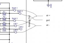
I'm still a bit puzzled how to connect the outputs when using it in dual mono configuration. Looking at the data sheet section dual differential setup, should it be like this?
Mono Left, Mode0: connect both Left1 and Right1 to XLR+; Left3 and Right3 to XLR -
Mono Right, Mode1: connect both Left1 and Right3 to XLR+; Left3 and Right1 to XLR -
and just out curiosity, would stacking multiple DAC boards, just like dddac, improve the quality even further?
Cheers,
c.
Hi Culture,
The easiest way to remember the mono wiring is this:
If the DAC is setup for the right channel mono then the right side output terminal will have the voltage output as marked. The left side will have the same signal, just inverse. So the LEFT side terminals are opposite as marked.
When the DAC is setup as a left channel mono then the left is normal, and the right reversed.
I have never tried stacking, and I am not even sure it would work. If some brave soul want to try it more power to them. 🙂
Cheers!
Russ
culture said:Hi Russ,
Thanks for the quick reply,
What i actually meant is, do I parallel the outputs (see attachment) on each board according to the used mode?
cheers,
c.
Yes. 🙂
Russ, (repost from head-fi)
Regarding the metronome - to enable ASRC, I will remove the Disable Jumper and configure switches as per recommended in the manual. Connect all wires except the SCK (PCM in) from the WM8804. Connect all wires (PCM out) to WM8740.
Leave the automute jumper on - it will automute if there is anything wrong with the signal.
Correct?
thanks
her shann
hershann said:Russ, (repost from head-fi)
Regarding the metronome - to enable ASRC, I will remove the Disable Jumper and configure switches as per recommended in the manual. Connect all wires except the SCK (PCM in) from the WM8804. Connect all wires (PCM out) to WM8740.
Leave the automute jumper on - it will automute if there is anything wrong with the signal.
Correct?
thanks
her shann
Correct, except for the automute, the automute will mute the signal when the device is not in a "ready" state. But very close!
You will also need to be sure the input format, output format, and mode settings are as you need.
Cheers!
Russ
Hi Russ,
I'm posting here as well as the support forum, as I'm not sure you're getting updates properly from there.
Slightly OT, I suppose, but it's all part of my Opus project.
I asked you about using balanced phones directly driven from the Ballsie and you suggested using the TXDs with the IA stage set to unity gain.
My questions are:
1. Can the new IVY be used in the same way?
2. Is the IA stage necessary when it's going to be used after the Ballsie?
It looks to me like I might be able to have it connected to both SE and balanced headphone sockets. Do you agree?
Opus kit received
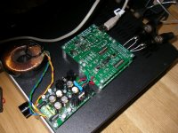
Just received my Opus kit, with Metronome and USB receiver. Quick delivery. Great quality! Setting it up was easy, and it worked perfectly right away. A great kit for beginners.
The sound was really nasty the first couple of hours, but after a little burn in period it sounds really great. There's no way you can get a better dac at this price.
Picture is from the test bench.
Attachments
- Home
- More Vendors...
- Twisted Pear
- Mr White's "Opus", designing a simple balanced DAC