This modular approach is paying off.. imagine various upgrades available as they are developed.. Nice!
Question then is: Can the Dual power the DAC as well as LCPS board? The dual is more friendly measurement wise for me, but if it is a lesser option, then not really an option.
Thanks for all the help to date!
Thanks for all the help to date!
pabbi1 said:Question then is: Can the Dual power the DAC as well as LCPS board? The dual is more friendly measurement wise for me, but if it is a lesser option, then not really an option.
Thanks for all the help to date!
Yes, you can use the Dual alone, and it should sound just fine. You would simply use the positive voltage out from the dual to power the DAC etc.
Cheers!
Russ
Variac said:This modular approach is paying off.. imagine various upgrades available as they are developed.. Nice!
Thanks! Yes, this was exactly the sort of thing I had in mind. I have something else up my sleeve but I will not spring it loose just yet. 🙂
BTW I already have the SRC4192 board laid out, and will get some prototype PCBs soon.
Cheers!
Russ
BTW I already have the SRC4192 board laid out, and will get some prototype PCBs soon.
Whoa... THANKS! 😀
Update on my hum problem: With the help of a more knowledgable DIYer over email. I've concluded that the zapfilter itself is faulty. Part of the circuit is drawing too much current which is causing its power supply to give off ripple noise.
Russ White said:
BTW I already have the SRC4192 board laid out, and will get some prototype PCBs soon.
Cheers!
Russ
I hope there is enough interest, I'm in for two boards.
So we can start to upsample our music to 192khz? 😀
Russ
I bought myself a MiniMac yesterday to serve as a music player. Because it only has an optical digital output I have to use the USB port. Am I correct that I would need than:
1x USB Receiver Module
1x Opus DAC Module
1x Ballsie
1x Dual Supply Module
1x LCPS
Regards
I bought myself a MiniMac yesterday to serve as a music player. Because it only has an optical digital output I have to use the USB port. Am I correct that I would need than:
1x USB Receiver Module
1x Opus DAC Module
1x Ballsie
1x Dual Supply Module
1x LCPS
Regards
GeWa said:Russ
I bought myself a MiniMac yesterday to serve as a music player. Because it only has an optical digital output I have to use the USB port. Am I correct that I would need than:
1x USB Receiver Module
1x Opus DAC Module
1x Ballsie
1x Dual Supply Module
1x LCPS
Regards
That would be optimal yes. 🙂
Cheers!
Russ
Thanks Russ.
From your website I have to order than an "Opus DAC + USB Receiver Combo" and an "Opus Ballsie Combo" to get what I just summed up.
Regards
From your website I have to order than an "Opus DAC + USB Receiver Combo" and an "Opus Ballsie Combo" to get what I just summed up.
Regards
thomaseliot said:
Pros and cons 🙂
If you want a silent PC music server without fans , it gets quite hot for a sound card. I burned my Emu1212m there. Whith SPDIF you have the clock in a high EMI box at least 1m. and 2 or 3 IC away from DAC, while USB clock is quietly 5cm from the DAC. An IC must extract the clock from SPDIF signal, while USB I2s has its own 2 cm cable.....
No, USB is still clocked by the computer as well due to the poorly designed USB Audio Class (though this may not be the case for all USB audio devices which may have custom drivers, it is true of the PCM2707). The problem is that the clock is embedded in the signal (just like SPDIF), but the interface is much more complicated, the timing events much less frequent, and the computer side of the equation has more variables. A good interface chip should do a decent job of recovering the clock, but there is certainly a lot more complexity involved in pulling it out from a USB signal than an SPDIF one. As I said in my previous post, the 12MHz crystal is there to make USB work, not to clock the I2S interface. That clock is generated by a PLL that stays in sync with the frames coming over USB, the timing of which controls the clock.
My educated guess is that the dedicated oscillator on a decent soundcard probably does a much better job of generating a good audio clock than the USB driver or transceiver IC on the computer's motherboard. Further, the SPDIF interface chip on the DAC should have an easier job recovering the clock than the USB chip.
There are of course reasons to use USB (I'm using a USB interface primarily right now), but I don't think it is possible for a good USB interface to be as good as a good SPDIF interface.
Russ, this modular stuff is great fun. I hope you're having as much fun designing the modules as we are using them.
error401 said:
There are of course reasons to use USB (I'm using a USB interface primarily right now), but I don't think it is possible for a good USB interface to be as good as a good SPDIF interface.
Quite clear, thanks 🙂
What do you think about the SRC4192 after the PCM2707?
Russ,
I think this module has a great future as CD player and existing DAC upgrade. 🙂
Why not to make this module 24bit/192Khz ready? While waiting for 24/192 music, If ever it will come, is it possible to use SRC4192 to upsample current 16/41.1 pcm?
SACD players do this trick with good results AFAIK.
I think this module has a great future as CD player and existing DAC upgrade. 🙂
Why not to make this module 24bit/192Khz ready? While waiting for 24/192 music, If ever it will come, is it possible to use SRC4192 to upsample current 16/41.1 pcm?
SACD players do this trick with good results AFAIK.
thomaseliot said:Russ,
I think this module has a great future as CD player and existing DAC upgrade. 🙂
Why not to make this module 24bit/192Khz ready? While waiting for 24/192 music
Or already pc based music servers!
Cd's already converted to 24bit/192Khz.
allan
thomaseliot said:Russ,
I think this module has a great future as CD player and existing DAC upgrade. 🙂
Why not to make this module 24bit/192Khz ready? While waiting for 24/192 music, If ever it will come, is it possible to use SRC4192 to upsample current 16/41.1 pcm?
SACD players do this trick with good results AFAIK.
Its is already ready for that.
I left all the I/O pins accessable via jumper, so all you need is an XO (of whatever quality you like, TENT, ECS etc) of the correct frequency to get any output you want. 44.1,48,96,192 whatever. 🙂
You could also down samplle if you needed to.
I run the XO clock to each PCM(as MCK) terminal block so you can run either of them in master mode. In most cases (out to an Opus DAC) you would use the input in slave mode (leave MCK open) and the output in master mode (MCK to the DAC).
Cheers!
Russ
TI Design Engineers rock!
Just got off the phone with a TI design engineer. I wanted to ask about some of the features of the SRC4192. One key thing I wanted clarification on was what happened when the "BYPASS" option is set and the output is in master mode.
Well pleasantly it turns out that in that case the output is synchronously (as opposed to asynchronously) re-clocked (at the same rate) with the XO on the RCKI pin. Thats pretty cool as it bypasses all filters, and introduces no group delay.
so you can do 44.1/16 to 44.1/16 and the bit clock, word clock, and master clock will be nice and tidy. 🙂
The bad news is that this bypasses the buffer(which has some nice benefits, but adds group delay) also, so you may actually do better not to use the bypass option. But I thought it was cool none the less.
A word about group delay. It is only important if you need to sync up multiple digital outputs, or DACs. For normal one DAC stereo use, it is of no concern at all. Even with multiple DACs, as long as you ran them all through SRC4192s configured the same way they would all be in sync.
Should be a nifty module. I look forward to playing with it. I made extra pads so one can use a DIP8 socket and try different XOs.
Cheers!
Russ
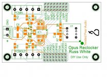
Reclocker perfect for CD-PRO folks
For those of you who wish to use the I2S out from the CDPRO modules into Opus this re-clocker module would certainly fit the bill, as you would no longer need to worry about obtaining a master clock. All you need as input into the ASRC is bitclock, wordclock, and data.
Cheers!
Russ
For those of you who wish to use the I2S out from the CDPRO modules into Opus this re-clocker module would certainly fit the bill, as you would no longer need to worry about obtaining a master clock. All you need as input into the ASRC is bitclock, wordclock, and data.
Cheers!
Russ
Russ, do you have some preference for SRC4192 over AD1896? The two are pin-compatible, so your design will work for both. SRC4192 is quite a bit cheaper.
- Home
- More Vendors...
- Twisted Pear
- Mr White's "Opus", designing a simple balanced DAC