If I just supply 30-40 V +- on the power transistors and 15-18 on the opamp I won't get more power without other modifications?
Well, extra gain might have been important in 1975, when 2n3055 had gain of 5.
Now it's not. Most 2n3055 have gain 20. Thompson says 2n3055 has 2.87 A SOA @ 40v. So if you double up on output transistors, and use the output structure in post 19, you might have 5.2 amps to play with if you have enough heat sink. You'll be voltage limited to about 1/2 the power supply rails, usually. V^2/R for 17v and 4 ohms is 75 W. Salvage a lot of heat sink for that. It won't put out that much on 8 ohms of course, with only 35 v rails.
Depends of course on how hard your op amp will drive it. No datasheets on a Mitsubishi anything I could find.
Last edited:
I'm on my phone now can't really see, doesn't Q1 Q2 need resistor from base to collector?
Here's Mitsubishi 5220 (I have the 8 dip, "not all in a line")
M5220L pdf, M5220L description, M5220L datasheets, M5220L view ::: ALLDATASHEET :::
Here's Mitsubishi 5220 (I have the 8 dip, "not all in a line")
M5220L pdf, M5220L description, M5220L datasheets, M5220L view ::: ALLDATASHEET :::
Attachments

Yes, the base stopper resistors from driver collector to output transistor base are good to prevent oscillation. Use 10 to 22.
Oh, this silly CFP thing in post 19 still doesn't have emitter resistors. Go back to something normal like eliott P3a but drive with an op amp, then resistor R6, then the two diode stack, then the drivers pushing outputs like darlingtons except have 100 ohm resistors from output base to the rails to bleed off the base charge while shutting off.
Well, mitsubishi 5220 bond wire limit 50 ma. PS limit +-22.5
Dip package limit 625 mw. thermal coefficient 6.25 mw/deg C
So analyze the maximum current you will can get out of the op amp using that thermal limit. The transistor end of the 47 ohm resistor is at 1.2 v when you're driving to max amount.
Warning, there is no heat sink for this DIP package. You're not going to get much out. Probably as good drive current wise as a DIP package LM4562. The higher R6 (op amp to diode stack) is the less likely you are to melt your precious 5220's. I'd start at 600 ohms then back off slowly.
Last edited:
It might be wiser to look at a worked-through design on those lines (no voltage gain) like this one, which does work as a simple current booster amplifier despite some criticism of the website. 22V supplies are the max. for TLE2141 and similarly rated opamps, so you need to account for mains supply fluctuations or use a regulated DC supply.Go back to something normal like eliott P3a but drive with an op amp, then resistor R6, then the two diode stack, then the drivers pushing outputs like darlingtons except have 100 ohm resistors from output base to the rails to bleed off the base charge while shutting off.
Well, mitsubishi 5220 bond wire limit 50 ma. PS limit +-22.5
18W Audio Amplifier - RED - Page1
BTW, the illustration I posted in #19 was just that - an illustration, not a complete schematic, for the purpose of clarity and an answer to the query; "....R14-17 what are they for?".
Really all these op amp driven CFP output schematics are just too weird.
commercial amps with op amp inputs and BJT transistors have emitters coupled to the speaker through emitter resistors.
See the commercially successful Peavey PV-4C a 200 W/ch into 4 ohms PA amp. https://www.elektrotanya.com/peavey_pv4c_sch.pdf/download.html
It has a two stage bjt transistor drive after the op amp, and uses a garden variety 4558 as input amp. It has a stack of diodes on the heat sinks as bias spreaders and heat sensors. You don't need to build the jfet-3380 DDT circuit, you don't need to build the VI limiters, the crowbar triac speaker protector is optional but I recommend it.
Your 5520 op amp as an input amp has no advantage over a 4558 because of the higher voltage rating. The output current is limited by the DIP package, since the output is clamped to +-1.2 or 1.8 v by the driver or predriver transistors. Boosting the rail voltage just increases the wattage burned to produce 1.8 v or its opposite, and hence cuts the current available due to the wattage limit of the heat-sinkless package.
So using both predriver and driver transistors like the PV-4C uses the op amp to best advantage.
If you want to skip the predriver transistor stage, buy an op amp with a heat sink. Some of them are called audio amp IC's, but the function is the same. I'm monkeying with an LM1875 today, to drive TV speakers direct replacing my TV sound circuit which sounds like monkeys in a tile room. Other audio amps are listed TDA. You find them some in boom boxes driving the speakers, if you want to salvage something instead of buying it. Best source of schematics I've found is datasheetcatalog.com the images are much clearer than alldata.
The Marshall Valvestate 8008 is a stereo 80 w/ch op amp driven amp which has some of the frills of the PV-4C left off. The schematic is on eserviceinfo.com search for valvestate 8080 or valvestate 8008. It also has a conventional (commercially successful) emitter follower output stage.
Note if you drop the rail voltage from 60 or so to 40 or so, you are leaving off the high wattage into 8 ohms capability, but if you have 4 ohm speakers, that just cuts the heat load sitting around idle.
Both those amps make the op amp supply voltage off the main rail voltage with a zener diode behind a series resistor. the 8008 has one op amp supply, the PV-4C has to have two and a two winding transformer because the PV-4C has flying speaker return. Flying speaker return allows the PV-4C to have the two amp channels paralleled for more wattage if they use the same input op amp. Another commercially successful feature you may not need, especially if you don't have a power transformer with two parallel windings.
Really for a first project these above have way more parts count than a 6 transistor APEX AX6 or a 7 transistor Bigun TGM8 covered on diyaudio. The op amp just complicates things instead of improving the sound, IMHO. The secret to my AX6 putting out 55 W on 8 ohm speakers with a single output pair, every transistor but the input transistor has a little cheap heat sink on it. I made the heat sinks out of scrap window frame by cutting & drilling holes, & I run it 18 hours a day sometimes. TIP41C/42C aren't total fidelity low Cob drivers or VAS transistors, but they sure waste the heat effectively.
Happy experimenting.
Last edited:
Bruno, that 4 transistor config allows the output voltage to swing rail to rail.
the 470 ohm feeds back the output to the emitter providing a gain of about 8 on each driver
the 470 ohm feeds back the output to the emitter providing a gain of about 8 on each driver
Offset controller
Hey everyone! If you wanted to change offset to close to zero, could you connect a trimpot from anode D1 with cathode in D2, also connecting R3 and R4 same trimpot? I have no knowledge of simulators. Can you help me please?
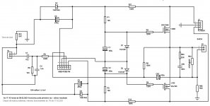
Something like this is more appropriate as a power amp:
PSU was made out of 200VA transformer (2x15V AC => +/-20V DC, single 10A diode bridge and 10,000uF/25V per rail is OK).
AD823 is supplied through 16V/1W Zener diodes and since it's a rail-to-rail OpAmp it will produce enough voltage swing to fully use the output stage made out of lateral mosfets source follower complementary pair. You can expect about 13W at 8 Ohms per channel or about 20W at 4 Ohms. Output stage has higher voltage power supply due to Vgs losses.
AD823 has JFET input and very low and stable DC offset so you can put volume pot at the input. Nothing to adjust - D1/D2 will reliably bias the output stage to about 150mA and the feedback loop will take care about DC offset.
Thermal stability is ensured through lateral mosfets' characteristics.
My build didn't need any external freq. compensation although it was used with 4-Ohm loudspeakers (medium to high reactive).
Similar results can be achieved with LM1875 chip but this design sounds noticeably better.
Hey everyone! If you wanted to change offset to close to zero, could you connect a trimpot from anode D1 with cathode in D2, also connecting R3 and R4 same trimpot? I have no knowledge of simulators. Can you help me please?
Hi augustoriodosul,
there's no need to adjust DC offset - AD823 will keep it on uV level through feedback loop.
there's no need to adjust DC offset - AD823 will keep it on uV level through feedback loop.
Hello Juma. Yes, you had stated that. But I used an AD825, and changed it to drive current output, with a .33R sense resistor. A 176 mV offset appeared, which decreases to 16 mV, if a 15K to R9 is used. But I think that changed the timbre of the machine, so I thought about adjusting it by trimmer. I appreciate if you can give me any indication. Best thanks.
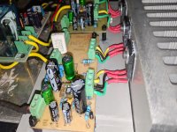
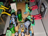
AD825+Lfet in test
Completed Juma amp #5, adapted for current mode or, as some call it, transconductance. I do not master assessment techniques in the scope but their response is flat from 1Hz to 500 KHz. Up to 5 MHz but with 180 degree phase rotation. Your job sounds very detailed, it must be AD825, fast. Powered by 4744 zener with 180R limiters. Voltage of 19VDC, Lfet Exicon EX10N20 and EX10P20, I am listening in pair with Vifa PL11WH09, free but cut at 90Hz (Linkwitz 48dB). Brazilian band UAKTI sounds very interesting. Thanks for everyone's information.
Completed Juma amp #5, adapted for current mode or, as some call it, transconductance. I do not master assessment techniques in the scope but their response is flat from 1Hz to 500 KHz. Up to 5 MHz but with 180 degree phase rotation. Your job sounds very detailed, it must be AD825, fast. Powered by 4744 zener with 180R limiters. Voltage of 19VDC, Lfet Exicon EX10N20 and EX10P20, I am listening in pair with Vifa PL11WH09, free but cut at 90Hz (Linkwitz 48dB). Brazilian band UAKTI sounds very interesting. Thanks for everyone's information.
Attachments
Last edited by a moderator:
- Home
- Amplifiers
- Solid State
- Mr. Rod Elliot's Amplifier "modding"