Both are electrical power amplifiers. Whether its voltage or current is fundamentally the same.. Two sides of the same coin, if you wish. They are just more suited towards one or the other.
Btw, you could achive the same using a power pentode in place of the mosfet, not just on the same level.
Btw, you could achive the same using a power pentode in place of the mosfet, not just on the same level.
Sorry I read your thread now for the 1st time. I never wanted to post pictures of my boarded test amplifiers for fear of stern warnings from MODS and others.... Yours is impressive! Mine are possibly too tidy in comparison.... Maybe I will post them in the future. 🙂
I love the parafeed approach. I have built them before as well, and they can indeed have low measured distortion. I would love to see how the simple 'FET gyrator compares to Tom's Miata regulator. Maybe the simple gyrator approach is good enough?
My own push-pull amplifiers were always sonically more satisfactory than any parafeed I built... Not quite as low on measured distortion, but far better bandwidth and transient response.
Best bass response is (from my experience at least) inherent with push-pull topologies. I would like to try and compare gyrator or pehaps more comprehensive regulator circuit (such as Tom Christian's Miata circuit) time permitting. Would HT+ swing be more or less essential for single ended then for push-pull? I need to consider this. My gut feeling is that single ended topologies would benefit from greater HT+ swing...
For the input tube is there any reasonable way to avoid the input coupling capacitor in your topology? besides input transformer?
Lastly.. silly question time here - why must we use the 'FET as a mu-follower? I think this is what goldenbeer and others might want to discuss as well... 😉
By virtue of separating their functions and purposes as much as possible, they really are not at all in the same component category in my opinion.
If you or anyone else wish to disagree, then fine. Call it a hybrid.
If you think my approach is not practical, you shouldn't build it. If you think it doesn't produce as good a sound as some other topology, you shouldn't build it. (I would agree on that count; I prefer my balanced reference amp to any SE amp I've heard. This thread is however limited to SE circuits.)
But once again I wonder what motivates this categorization - I honestly believe the circuit that will be the final product of this experiment (once I get the next two steps done) is the best SE topology I've come across. SS or tubes or hybrids included. Balanced circuits are another topic and outside of this. Please go ahead and present your circuits, what you honestly believe to be better or best you've found (nobody has seen or heard everything, so 'best' is implicitly always subjective).
In the final version I'll be substituting a capacitor with a FET. I wonder what people will say about that... It does both measure and sound better but I don't know if it's going to be considered unfair cheating as well. =)
I never wanted to post pictures of my boarded test amplifiers for fear of stern warnings from MODS and others.... Yours is impressive! Mine are possibly too tidy in comparison.... Maybe I will post them in the future. 🙂
I know what you mean. There are some serious construction pics on this board. I guess I hoped nobody would comment too harshly because they would be simply awestruck on my massive 100µF / 3kV film cap serving as the cathode cap.
I would love to see how the simple 'FET gyrator compares to Tom's Miata regulator. Maybe the simple gyrator approach is good enough?
What is this Miata regulator? It sounds like it's a reg, not a plate load? Please elaborate. My circuit has a simple 2 FET regulator.
My own push-pull amplifiers were always sonically more satisfactory than any parafeed I built... Not quite as low on measured distortion, but far better bandwidth and transient response.
Bandwidth and transient response can be made better than trad. PP usually has. In distortion the balanced topology (at least with modern HYBRID assistance) will always win though.
The next mod I'll present in this thread will improve SE transient response significantly.
Would HT+ swing be more or less essential for single ended then for push-pull? I need to consider this. My gut feeling is that single ended topologies would benefit from greater HT+ swing...
You are correct. SE needs a higher B+ to achieve the same output.
For the input tube is there any reasonable way to avoid the input coupling capacitor in your topology? besides input transformer?
Use any bias method. I prefer fixed grid bias. For higher current LED bias is good also.
The best way to get bias in my opinion would be to use a MOSFET at the input that's gate is at DC ground, directly connected to amp input. FETs source is directly connected to input tube's grid (tube has cathode grounded). Under the FET would be a CCS and a -20V or so negative supply. Completely transparent and directly coupled; provides fixed grid bias and any possible grid current elegantly without capacitor. =)
In practise I can live with the cap.
Lastly.. silly question time here - why must we use the 'FET as a mu-follower? I think this is what goldenbeer and others might want to discuss as well... 😉
What do you mean? You mean why not use a tube as the top device?
I started out in totem pole topology using a 6SN7 SRPP. Little bit better than resistor. Then I converted the top 6SN7 to mu follower; better than SRPP. Then I read up on a bunch of theory about what the mu follower actually does and what parameters are critical in it. I changed the top device to 6C45P, since it has higher gm. It performed better. Then I read and thought some more, and instead of going for the pentode (too many heater supplies as it was), I went straight for the MOSFET. It performed orders of magnitude better than the previous versions, and was cheaper than all of them (except resistor).
That's why I use a FET as the top device in a mu follower; because it sims, measures and sounds better, while costing next to nothing.
Please go ahead and present your circuits, what you honestly believe to be better or best you've found
Have a look at the attached circuits.
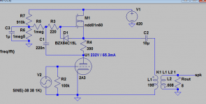
The 1st is a optimized 2a3 circuit as per your suggestions.
It dissipates 27.5W idle power and puts out ~4.5W at 1.64% THD.
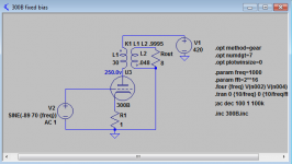
The 2nd is a rather unoptimized 300b circuit, more or less straight from the datasheet. It is NOT the best I found in any way.
It also dissipates 27.5W idle power and puts out 4.5W at 1.88% THD.
(H3 however is significantly lower at ~0.04% vs 0.4% for the 2a3 circuit)
The 300b circuit has quite a bit more headroom. It can put out 7.5W max.
It also has 1 mosfet and 2 caps less in the audio path.
So again, what's the point of the gyrator loaded power stage?
Attachments
Last edited:
Tom's Miata regulator is this:
http://www.neurochrome.com/wp-content/uploads/2012/03/MaidaReg_1p0_Schematic.png
He is on this board and posts too...
I suppose you did not understand what I assumed would be obvious, but then I don't know what your "regulated B+" is coming from...
What I mean is this, I can see using the 'FET as a MU follower on the input, but why go parafeed at all on the output? If your regulated B+ is very good then you could lose the coupling cap and mu Follower 'FET and do direct coupled single ended...
edit: oops, goldenbeer just posted something quite similar. 🙂 In any case, I don't mind the extra components. I just question adding anything into the audio path even if they are claimed to be "transparent" etc..
Last edited:
You are correct. SE needs a higher B+ to achieve the same output.
Not only that. The B+ needs to be able to swing quite a bit. A choke can do this exceptionally well. I have not made measurments on regulated supplies yet though. The one posted by tomchr is one I would like to test soon.
Here is his thread:
http://www.diyaudio.com/forums/tubes-valves/209067-21st-century-maida-regulator.html
In distortion the balanced topology (at least with modern HYBRID assistance) will always win though.
What does HYBRID stand for? If it is in all caps then it is surely an acronym. 😉
I never forget this advice I once received: Cardboard has very low distortion. It just does not sound good.
I have heard many amplifiers with very low distortion values. Astonishingly few were interesting. Same goes for hypebrid amps. That does however not mean that regulators, cascoded 'FET's and other things are not possible or even better. Cascoded 'FET can be very useful. Same for CCS's. Today things are different, and I recognize that.
We have been through this before, but when someonesays "balanced topology" I immediately think "rusty old beat-up push-pull dynaco kit". Don't doubt it, that is exactly what pops into my mind. There is seriously good "balanced" sound in those old dynaco's. On a good day I might think about my lovely old Telefunken ribbon microphones instead. They are also "perfectly balanced". High-End marketeers have overused "balanced" for so many years now that I just can't bear to hear it anymore. I'm not alone on this.
Believe it or not, I actually started with tubes/valves because it is cheaper and more accessable than truely high end solid state. The best phono amplifier I have ever had the pleasure to audition is full solid state. Unfortunately it is also exquisitely expensive and impossible to duplicate.
Last edited:
Have a look at the attached circuits.
The 1st is a optimized 2a3 circuit as per your suggestions.
It dissipates 27.5W idle power and puts out ~4.5W at 1.64% THD.
The 2nd is a rather unoptimized 300b circuit, more or less straight from the datasheet. It is NOT the best I found in any way.
It also dissipates 27.5W idle power and puts out 4.5W at 1.88% THD.
(H3 however is significantly lower at ~0.04% vs 0.4% for the 2a3 circuit)
The 300b circuit has quite a bit more headroom. It can put out 7.5W max.
It also has 1 mosfet and 2 caps less in the audio path.
So again, what's the point of the gyrator loaded power stage?
Ok, let's go thru this point by point:
1) You simmed at or very near the clipping point. It is true that the gyrator circuit clips much less pleasantly than the traditional circuit. This is not an issue if the circuit is otherwise designed to have a very fast / instantaneous overload recovery. RC cathode bias is not that (referring to my first version posted in this thread).
2) If you feel you need / want a lot of power, I will flat out say this circuit is not for you.
I'll specify the point of this circuit: it is for getting the best performance (THD, freq response with a chosen OT, ability to use much much cheaper OT) out of the tube you have chosen to work with. I will demonstrate this below.
3) Sure, you can get similar THD at 1 kHz at the same power level with a bigger tube. Well, when you have that bigger tube, why settle for that same distortion? At 4.5W the 300B with parafeed and gyrator plate load at 1 kHz sims:
Total Harmonic Distortion: 0.65%
If I wanted to use the 300B, I would not settle for that 1.8% TDH, I would want better. For the price of using a Hammond general purpose OT (yes, I'm serious) instead of big big bucks (300B needs a bigger OT than 2A3) OT, I could build a bigger PSU (higher B+) and make that happen. And, even if it cost more to make that higher B+, I'd go there anyway: because I want that lower THD and all the other benefits.
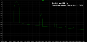
4) Other benefits? Glad you asked. When you use OT as plate load, in series feed mode (the trad set up), you get worse and worse performance when you go down in frequency.
I did the sims with 300B both in series feed (trad) and gyrator loaded parafeed, at 4.5W RMS output, on 30 Hz:
Total Harmonic Distortion: 0.60% gyrator loaded parafeed
Total Harmonic Distortion: 2.25% series feed trad.
5) When I post square wave measurements of my experiment (OT is Hammond 125D for push pull, 25 euros or so) at 15 kHz or 20 kHz, I'll ask you how much you have to pay to make that happen with a series feed circuit.
Most (nice to listen to) music doesn't contain a lot of square waves, that's true. But you know what that means for transient response, the 'impact' factor I was speaking earlier. I personally find it to make the music a whole lot more lively and enjoyable. That is why I wrote I find most trad SEs to seem 'slow'.
6) Ok, you could once again go bigger, after the 300B, to get better results at 4.5W at 1 kHz or whatever higher power output you choose for the 300B. What would you use?
In summary: gyrators provide better results with a given tube.
They are not, however, for people who are concerned with efficiency, or people who are looking to get really big power. They are not for people looking to cut costs; however most will find that they get better results even with much cheaper OT's, and might make even or come a little ahead, costwise.
I never forget this advice I once received: Cardboard has very low distortion. It just does not sound good.
That is a fair concern. I do not know how to respond to that except by giving more of my subjective perceptions. Try it out and tell others what you thought of it.
I have heard many amplifiers with very low distortion values. Astonishingly few were interesting.
I completely agree. I've stressed on many occasions - including elsewhere in this thread - that I think it not at all inconsequential how a certain low THD value is achieved. Not all low THD is created equal, at least such has been my perception.
Have you ever heard a circuit I've been describing? You do realise it works quite differently than most amps, so it might not be wise to prejudge it (except of course on technical terms).
About the balance act:
I get that and agree it's been over/misused. However, it is completely technically accurate: my balanced amp really, measurably, is completely and fully balanced, therefore I will continue to use that term. =)
The best phono amplifier I have ever had the pleasure to audition is full solid state.
Ok I realise I shouldn't say this, because I really haven't heard very many phono amps (unlike power amps), but I can't resist: you haven't heard my fully balanced phono stage. =D
It's probably not the best in the world, but it's the best I've ever heard! (I do have very limited experience hearing different designs specifically regarding phono amps.)
Mind you, same output power level as well as idle power!3) Sure, you can get similar THD at 1 kHz at the same power level with a bigger tube.
Low frequency sim results depend first and foremost on the transformer model, not the tube or circuit.4) Other benefits? Glad you asked. When you use OT as plate load, in series feed mode (the trad set up), you get worse and worse performance when you go down in frequency.
I did the sims with 300B both in series feed (trad) and gyrator loaded parafeed, at 4.5W RMS output, on 30 Hz:
Total Harmonic Distortion: 0.60% gyrator loaded parafeed
Total Harmonic Distortion: 2.25% series feed trad.
In the real world, it's true you need a very good OPT to achieve good performance in series feed. But they are available, even if it's at a cost.
But glad you raised this. While THD is comparable between your gyrator topology and traditional series feed for the same output and idle power, the harmonics profile is not. The 300B's H3 and higher harmonics are 10x less! 😀
How 'bout that?
My summary, the gyrator loaded power stage is nothing special. It's performance is comparable to simply using a bigger tube in standard series feed.In summary: gyrators provide better results with a given tube.
The harmonics profile is even worse, as is the Max power output. It places additional and large caps in the audio path.
It's damping factor is significantly higher (strange you didn't mention this so far) and you can use a cheaper OPT though.
Slew rate might be thought important for dynamics and impact of the audio but if uneven harmonics are double or worse it's a born dead child. If the damping factor is not helping either (what I believed to be) ....

Appreciate the effort you put in to this work, for the benefit of all.
Appreciate the effort you put in to this work, for the benefit of all.
Last edited:
Mind you, same output power level as well as idle power!
Once again; for people concerned with efficiency: you should look elsewhere.
Low frequency sim results depend first and foremost on the transformer model, not the tube or circuit.
Yes. In reality the difference between these two topologies is much greater. This series feed THD figure is quite optimistic.
This is usually the first thing one notices when listening to a gyrator SE circuit; much more bass definition.
In the real world, it's true you need a very good OPT to achieve good performance in series feed. But they are available, even if it's at a cost.
Yes. And people who would rather use a big OT, than some SS assistance absolutely should buy that big OT.
But glad you raised this. While THD is comparable between your gyrator topology and traditional series feed for the same output and idle power, the harmonics profile is not. The 300B's H3 and higher harmonics are 10x less! 😀
How 'bout that?
I haven't ever simmed a 300B before, nor built with it. Based on your and my own sims I'd add that the gyrator circuit apparently (I am interested why this is) is not suitable for it.
Categorical caveat addition: the gyrator circuit is not for over 3W use. Like I said on numerous occasions before, if you need / want more power, look elsewhere.
Now let's look at the harmonic performance. Your claims about it are utter bunk (within the specified power range).
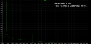
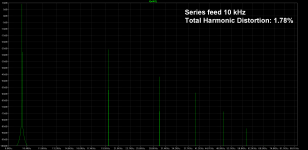
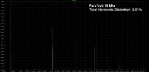
Attached are FFTs with THD figures added of 2A3 at 1W RMS output power, both in gyrator parafeed topology and traditional series feed.
Like I wrote earlier in this thread: the harmonics profile is exactly the same, only there's less distortion overall.
Save the pics on your computer, and look at while switching between them. They have the same scales for ease of comparison.
Where is there a difference (to the gyrators loss) in odd harmonics? To my eye, the gyrator seems to win all the comparisons. This is also self evident when doing actual listening tests.
My summary, the gyrator loaded power stage is nothing special.
I cannot comment on specialness, but it does provide the best performance that can be had out of a chosen low power tube in SE, open loop.
It's performance is comparable to simply using a bigger tube in standard series feed.
Only at 1 kHz. And, not when comparing square waves. And, only if the lower power tube is very close to clipping in the comparison (like I said, the gyrator clips with more odd harmonics; this is not however audible in well designed amps).
The harmonics profile is even worse
Completely false. Look at the FFTs attached and tell me how one could reach that conclusion.
as is the Max power output
True. Once more; if you need/want power, look elsewhere.
It places additional and large caps in the audio path.
I'll personally take a low impedance driven film or paper in oil cap anyday over all the parasitics in a series feed OT. But, for people who choose otherwise, this is not their topology.
Attachments


Slew rate might be thought important for dynamics and impact of the audio
Yes, it is.
but if uneven harmonics are double or worse it's a born dead child.
Thankfully they are not. The spectrum is exactly the same as trad SE, except when very close to clipping.
If the damping factor is not helping either (what I believed to be) ....
What do you mean?
Appreciate the effort you put in to this work, for the benefit of all.
Thank you!
I apologize for the slightly off-topic question, but I cannot recall seeing the answer to this even after reading several threads over gyrator use...
Is the MOSFET gyrator load really just a (here's that word again) hybrid mu-follower? Or, is it considered something different since the resistor between the tube and the load is considerably smaller than would be the case in a mu-follower? At any rate, the circuits look very similar...
Is the MOSFET gyrator load really just a (here's that word again) hybrid mu-follower? Or, is it considered something different since the resistor between the tube and the load is considerably smaller than would be the case in a mu-follower? At any rate, the circuits look very similar...
Is the MOSFET gyrator load really just a (here's that word again) hybrid mu-follower?
The short answer is yes. You can do similar things with a tube, but MOSFET has certain characteristics that make it better suited.
Of course you can also put the entire topology into question... but that's a complex discussion.
Last edited:
I apologize for the slightly off-topic question, but I cannot recall seeing the answer to this even after reading several threads over gyrator use...
Is the MOSFET gyrator load really just a (here's that word again) hybrid mu-follower? Or, is it considered something different since the resistor between the tube and the load is considerably smaller than would be the case in a mu-follower? At any rate, the circuits look very similar...
This is completely on topic!
Like soulmerchant wrote, yes, it is a mu follower. In both cases the top device is a follower (if it's a tube, a cathode follower, if a FET, a source follower) and the setup utilises the whole µ of the bottom tube (or approaching it).
The performance of the mu follower can be simplified to rely on the top device having greater control of the current flow thru the system. Therefore best results are had, when the top device is able to completely overpower the bottom devices transconductance. Hence, FETs.
MOSFETs also require much lower voltage headroom (voltage swing is limited with tube as top device) and provide lower output impedance. Also no heater and cheap price. They do not in any way colour the sound when not near clipping; the bottom device contributes all of the harmonic signature.
A couple of pages back I wrote about my journey in totem pole gain stages with different top devices.
I hate to be the one to mention this... but such use of mu-follower topology is superb in push-pull circuits. I know, since I have built them this way... 😉 It is nothing new though. I remember bespoke amplifiers from the early 90's that exploited this topology.
From my experience it is not quite as successful in single ended... perhaps for reasons already mentioned. But I try to keep an open mind. One thing for certain - it can be done inexpensitvely, so is definitely worthy of investigation/experimentation.
From my experience it is not quite as successful in single ended... perhaps for reasons already mentioned. But I try to keep an open mind. One thing for certain - it can be done inexpensitvely, so is definitely worthy of investigation/experimentation.
I hate to be the one to mention this... but such use of mu-follower topology is superb in push-pull circuits. I know, since I have built them this way... 😉 It is nothing new though. I remember bespoke amplifiers from the early 90's that exploited this topology.
From my experience it is not quite as successful in single ended... perhaps for reasons already mentioned. But I try to keep an open mind. One thing for certain - it can be done inexpensitvely, so is definitely worthy of investigation/experimentation.
Funny you should mention...
You hadn't seen the thread(s) discussing my balanced topology?
- Status
- Not open for further replies.
- Home
- Amplifiers
- Tubes / Valves
- Mr.Curwen's single ended adventures