Not only that. The B+ needs to be able to swing quite a bit. A choke can do this exceptionally well.
A choke or a series feed OPT. I'm swinging nearly 5kV in my SE amps; transient response and bass impact are to die for. Literally if you're not careful ;-)
But I do use the gyrator plate load/mu-follower in the driver stage on top of the 6E5P...
Attachments

Funny you should mention...
You hadn't seen the thread(s) discussing my balanced topology?
Old, old, old stuff, sorry to inform you. 😉 Very few truly new things are invented today. Mostly re-discovered.... I borrowed this type of excellent topology myself long ago, and have been aware of it since the 90's. If you do a search on this board and look for old threads you might be surprised.
Last edited:
A choke or a series feed OPT. I'm swinging nearly 5kV in my SE amps; transient response and bass impact are to die for. Literally if you're not careful ;-)
But I do use the gyrator plate load/mu-follower in the driver stage on top of the 6E5P...
I don't need quite that much power, but it is truly impressive!
[...]
Now let's look at the harmonic performance. Your claims about it are utter bunk [...]
We agree to disagree then. Or, your claims are utter bunk, if you wish...
Your basis for comparison seems to be the same toob. Obviously, if you add a ss gyrator on top, providing low dc resistance and high ac impedance drive, distortion comes down, while power consumption roughly doubles.
My basis for comparison is SE output stages running at the same identical idle power consumption. An here the picture is not so clear. The gyrator loaded parafeed topology scores on damping factor, while the usual series feed topology scores on headroom (= power efficiency) and (less) higher harmonics.
Magz, that thing must really cut out of your house heating bills! I've been designing (dreaming of) an amp that could swing 1200 V differential voltage, for ESL speakers. Scaling up quickly gets very expensive... Incidentally that's why I got a pair of those 100µF / 3kV film caps, one of which is in the pictures in the first post.
soulmerchant: I was not aware of that. After I posted a few times my balanced schematics with gyrator plate loads and CCS tails, I found out that Morgan Jones had presented essentially the same circuit in one of his books (he apparently used three CCSs and not gyrators). The general reception was that it's completely crazy and/or doesn't work at all (with some exceptions). Well, like you said, nothing new under the sun.
goldenbeer:
I get that you are comparing two different tubes. That's not ok though, to borrow a phrase from you: it's apples and oranges. You can with a couple of sims clearly see for yourself that the gyrator does not produce more odd or higher harmonics within it's power range. It simply doesn't.
The improved bass performance cannot be replicated in series feed (open loop) without great expense, and I would argue, not at any price. Coils inherently perform poorer with falling frequency, cheap or expensive.
Audio design is full of compromises; this topology presents a certain set of drawbacks, and certain set of advantages. If you say that one of the drawbacks is higher/odd harmonics, you must specify that these drawbacks only occur in certain conditions. It is not a universal. This topology has a specified power range, and within it it performs very well.
soulmerchant: I was not aware of that. After I posted a few times my balanced schematics with gyrator plate loads and CCS tails, I found out that Morgan Jones had presented essentially the same circuit in one of his books (he apparently used three CCSs and not gyrators). The general reception was that it's completely crazy and/or doesn't work at all (with some exceptions). Well, like you said, nothing new under the sun.
goldenbeer:
This circuit is not for most. It is for some people though, and I present it to generate discussion and maybe somebody tries it out and enjoys his music more, with lower distortion. It is completely understandable to reject this topology because it's too inefficient, if that's important to you, or because it cannot be used to get more than a couple of watts of power. Or, because of non-audio reasons, like wanting to keep to tradition at the expense of fidelity (as long as one is honest about it). However I will not agree to disagree on the harmonics:We agree to disagree then.
No. Look at the FFTs I posted at 1W and tell me where the gyrator has more higher harmonics.while the usual series feed topology scores on headroom (= power efficiency) and (less) higher harmonics.
I get that you are comparing two different tubes. That's not ok though, to borrow a phrase from you: it's apples and oranges. You can with a couple of sims clearly see for yourself that the gyrator does not produce more odd or higher harmonics within it's power range. It simply doesn't.
The improved bass performance cannot be replicated in series feed (open loop) without great expense, and I would argue, not at any price. Coils inherently perform poorer with falling frequency, cheap or expensive.
Audio design is full of compromises; this topology presents a certain set of drawbacks, and certain set of advantages. If you say that one of the drawbacks is higher/odd harmonics, you must specify that these drawbacks only occur in certain conditions. It is not a universal. This topology has a specified power range, and within it it performs very well.
Last edited:
Every tube I've measured gets lower distortion with a higher load Z. Mainly 2nd harmonic residual. Seems to me, the issue here is due to different tubes, or apples to oranges being compared.
I occasionally hear the idea of a "switched HF inductor" mentioned for a lossless Hi-Z plate load. And I understand that David Berning's SE Siegfried Ampl. uses such a thing of a sort. The schematic is on the web (below). However, I can't see how commutating the audio into HF across a small HF inductor could generate 2X B+. Where does it get the audio freq. memory for the integrated current?
Maybe if it had TWO switched inductors, one for each polarity of the audio signal to integrate separately. Probably the single HF inductor in the Siegfried is only being used as a lossless CCS. If someone figures this out for a 2X B+ design to emulate a conventional audio SE inductor, please enlighten us all.
http://www.triodeel.com/images/sieg1.gif
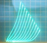
Of course a better tube does always help things. But 300B?
The $1 tube that eats 300Bs for breakfast (50 mA/div, 50V/div):
And then the $5 one that's even better.
I occasionally hear the idea of a "switched HF inductor" mentioned for a lossless Hi-Z plate load. And I understand that David Berning's SE Siegfried Ampl. uses such a thing of a sort. The schematic is on the web (below). However, I can't see how commutating the audio into HF across a small HF inductor could generate 2X B+. Where does it get the audio freq. memory for the integrated current?
Maybe if it had TWO switched inductors, one for each polarity of the audio signal to integrate separately. Probably the single HF inductor in the Siegfried is only being used as a lossless CCS. If someone figures this out for a 2X B+ design to emulate a conventional audio SE inductor, please enlighten us all.
http://www.triodeel.com/images/sieg1.gif
Of course a better tube does always help things. But 300B?
The $1 tube that eats 300Bs for breakfast (50 mA/div, 50V/div):
And then the $5 one that's even better.
Attachments

Last edited:
However I will not agree to disagree on the harmonics:
No. Look at the FFTs I posted at 1W and tell me where the gyrator has more higher harmonics.
I get that you are comparing two different tubes. That's not ok though,
I was comparing two most similar tubes (2a3 vs 300b). You could do the same with a 45 vs 2a3 (which is essentially 2 45s in parallel). Or do the same with a 2a3 vs JJ 2a3-40, if you want to do the comparison with an identical tube.
First, improve response by adding a gyrator on top and going parafeed. Then, improve response by raising the operating point such that idle power matches that of the gyrator loaded stage, while retaining single feed topology, preferrably with a higher primary inductance OPT.
Results will always be very similar. 3rd and higher harmonics (at any given output power) of the series feed topology will be lower though.
Your impression of improved bass response might be due to the higher damping factor of your gyrator stage, but this depends first and foremost on your speakers. Most improve their bass response with higher DF.
As another little contribution to the subject, please have a look at attached diagram.
Once you accept you will use only the voltage amplification characteristics from the tube(s), and allow all other stuff like active plate loads, current drive, ccs and such to be taken care of by SS parts, just be brave and consequent, and wonderful opportunities open up.
~3.3W output, <1% THD with classic SE distortion spectrum, single stage, damping factor ~8. OPT can be some mains toroidal.
Attachments
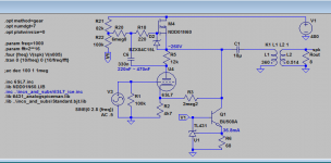
Yes, a small bit of positive feedback, to boost input sensitivity a little.
Curiously, it appears to raise H2 just a tiny bit, while lowering H3 and higher harmonics.
Curiously, it appears to raise H2 just a tiny bit, while lowering H3 and higher harmonics.
One less distorting, bandwidth limiting, phase shifting, power limiting component in the audio path?
http://www.amplimo.nl/images/downloads/ds vdv/vdv1070uc.pdf
sacd capable, can a class d do that?
...~3.3W output, <1% THD with classic SE distortion spectrum, single stage, damping factor ~8. ...
Does a mu-follower count as a single stage circuit? Doesn't the signal pass through two active devices (voltage gain from tube, current gain from the cathode/source follower), making it a two stage circuit?
Anyway, I have simulated similar circuits (mu-follower straight to OPT via parafeed connection) myself in SPICE and found that the simulations looked good, but I've never built one since I was unsure whether the real-world performance would mirror the simulation. Has anyone tested such circuits? If so, how is the performance?
Last edited:
Smoking-amp...Could you post the identity of the tubes that generated the tube curves you posted?
twystd
Of course a better tube does always help things. But 300B?
The $1 tube that eats 300Bs for breakfast (50 mA/div, 50V/div):
And then the $5 one that's even better.
twystd
Last edited:
The tube types are visible on the file name that comes up when the screen cursor is placed over the pics. 21HB5, and 6HJ5
However, George (Tubelab) says the 6HJ5s are mostly gone. Someone in Hong Kong has been buying up the entire tube stocks (10,000s+) of tubes that get mentioned here as being good (like days later). You might be able to find some 21HB5 at $6 now, 21JV6 is nearly the same (different base) and is $3. I don't know how many are left. The reason those curves look so good, is that they are curve traced in a Schade Fdbk configuration. The Schade Fdbk works wonders for most TV sweep tubes. I won't be mentioning any more super tubes, the hobby tube supply has been nearly wiped out.
However, George (Tubelab) says the 6HJ5s are mostly gone. Someone in Hong Kong has been buying up the entire tube stocks (10,000s+) of tubes that get mentioned here as being good (like days later). You might be able to find some 21HB5 at $6 now, 21JV6 is nearly the same (different base) and is $3. I don't know how many are left. The reason those curves look so good, is that they are curve traced in a Schade Fdbk configuration. The Schade Fdbk works wonders for most TV sweep tubes. I won't be mentioning any more super tubes, the hobby tube supply has been nearly wiped out.
Last edited:
- Status
- Not open for further replies.
- Home
- Amplifiers
- Tubes / Valves
- Mr.Curwen's single ended adventures