This is for documenting my single ended experiment.
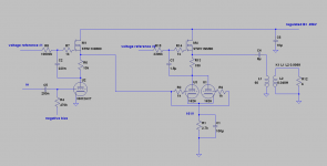
In the other thread with the 2A3 single ended schematics came up the issue of whether or not it is even possible - or further, beneficial to good fidelity - to put gyrator plate loads on 2A3 tubes.
Making it more challenging, to make it DC coupled.
So the objective is to make a breadboard experiment that
1) proves that the DC coupled circuit can and will find it's stable op points safely and reliably with gyrator plate loads
2) there are sonic benefits to gyrator plate loads even in SE output stage
Now unfortunately I don't have an 2A3 at hand, so we agreed on parallel 1626 with 60mA current. This is fitting, since most 2A3 are double plate tubes anyway.
To my disappointment, the transformers I had on the shelf only gave me 450V DC regulated, so I had to separate the two objectives. The DC coupled version is not as good as I hoped to make, since I was hoping to have at least 520V to work with.
So, DC is just to make a point; it can be done. If voltage allows, it can be done with very good results. I will prove point 2 with a more sensible circuit with measurements in a later post. Since the voltage headroom is so low on the DC version, I didn't do measurements yet.
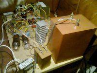
I only have an old cell phone for pictures and video. I'll take better pics in daylight. =)
Video is dark and sound useless, but here's a clip anyway: https://www.youtube.com/watch?v=xVTaiMMTCu8
Volume was much louder than the cell phone video indicates. The sound coming from speaker made the mic clip. Bass was deep and forceful; not as detailed and engaging as my 4P1L balanced amp (4P1L amp measured flat from 10 Hz up; something similar expected here). Mids were close to balanced reference amp; highs less detailed, less '3D'.
I listened about 30 minutes. After turn off, I tried the 1626's plate load heat sink; it wasn't warm at all. In the next version it'll be warm. This size sink is going to be ok for 10W dissipation I suspect.
All in all, despite the low headroom caused by DC, this was a pretty good amp; I was pleasantly suprised. Now that we know it'll find stable op points with gyrators In the next post I'll make it much better.
In the other thread with the 2A3 single ended schematics came up the issue of whether or not it is even possible - or further, beneficial to good fidelity - to put gyrator plate loads on 2A3 tubes.
Making it more challenging, to make it DC coupled.
So the objective is to make a breadboard experiment that
1) proves that the DC coupled circuit can and will find it's stable op points safely and reliably with gyrator plate loads
2) there are sonic benefits to gyrator plate loads even in SE output stage
Now unfortunately I don't have an 2A3 at hand, so we agreed on parallel 1626 with 60mA current. This is fitting, since most 2A3 are double plate tubes anyway.
To my disappointment, the transformers I had on the shelf only gave me 450V DC regulated, so I had to separate the two objectives. The DC coupled version is not as good as I hoped to make, since I was hoping to have at least 520V to work with.
So, DC is just to make a point; it can be done. If voltage allows, it can be done with very good results. I will prove point 2 with a more sensible circuit with measurements in a later post. Since the voltage headroom is so low on the DC version, I didn't do measurements yet.
I only have an old cell phone for pictures and video. I'll take better pics in daylight. =)
Video is dark and sound useless, but here's a clip anyway: https://www.youtube.com/watch?v=xVTaiMMTCu8
Volume was much louder than the cell phone video indicates. The sound coming from speaker made the mic clip. Bass was deep and forceful; not as detailed and engaging as my 4P1L balanced amp (4P1L amp measured flat from 10 Hz up; something similar expected here). Mids were close to balanced reference amp; highs less detailed, less '3D'.
I listened about 30 minutes. After turn off, I tried the 1626's plate load heat sink; it wasn't warm at all. In the next version it'll be warm. This size sink is going to be ok for 10W dissipation I suspect.
All in all, despite the low headroom caused by DC, this was a pretty good amp; I was pleasantly suprised. Now that we know it'll find stable op points with gyrators In the next post I'll make it much better.
Attachments

Member
Joined 2009
Paid Member
It looks a lot like a parafeed circuit that you have built. The OPT does not get dc because it is blocked by the 8uf cap that you have on the top of the primary and you are providing a gyrator in place of the plate choke. Using the circuit that you have designed, did you calculate the proper value for the blocking cap or just put in what you had on hand? I'm wondering if that would make a difference in the fidelity of the amp that you have breadboarded......
Bigun, thanks! This time the base board has hardly any stuff on it; two channels of balanced amp gets it full. Maybe going mono from now on would simplify things...
lexx21:
It is in fact a parafeed circuit. The cap's value is determined by simple RC calculation; 4µF and 10k impedance give 3.97 Hz as -3dB point. This is satisfactory. I try to get the C as small as possible, to ensure best quality (smaller caps have consistently proven better to my ears), without hurting low end extension. In reality since I run the OT with a 4 ohm secondary always (with all loads), the frequency response is usually completely flat down to 10 Hz or so.
This time I run the OT 5k : 4R, so I doubled the C to 8µF to keep the frequency response the same.
I've built a number of SE amps like this; the ones that got their own enclosures ("that made it") are no longer in my possession except one that is wrapped up and stored away waiting for cleaning and rebuilding (cap blew up and goo'ed the insides).
They've been small current for small heat, small power. 4P1L SE amp had 20mA idle current, that was the biggest. The point of this experiment is to use large current, to show it can be done, and to provide some measurements.
[SIZE=-1][SIZE=-1][/SIZE][/SIZE]
Member
Joined 2009
Paid Member
Can you use the gyrator on the input tube to drive the output tubes into A2 ?
It can be done, but in this topology, there is no additional power to be gained.
The top mosfet has to deliver the standing current thru the power tube (which is nearly constant) + the AC current thru the OPT. Hence the (low distortion) AC current swing (pk-pk) thru rhe opt is limited to 2 times the standing current thru the power tube. Beyond that, the "negative" half wave is cut at 0 mA.
goldenbeer is correct. Also, I'd put a small current CCS from plate load source to ground, if the preamp tube is 12AX7 or similar high rp.
In the other thread, I wrote
to which disco responded:
Yes, you are correct. However, that is within that specific topology. In another topology, say with a gyrator load, tube aging is not an issue at all. Also different tube brands are not an issue in any way.
You are comparing tubes inside a specific topology (Darius follower). I meant universally, different topologies can deliver very much varying results. Not just about the same as you previously wrote. And, some topologies are pretty much immune to brand or age issues.
In the other thread, I wrote
Sims are what they are. However I could not disagree more on the distortion varying more between tube brands and such than between topologies. Load lines matter. A lot; no two different brand in spec tubes make even 5% as much difference as two different load lines. This is very easily heard in my experience.
to which disco responded:
ri of a worn out tube is higher than a fresh tube, one would expect that property to be noticeable in marginally designed circuits, or in a circuit where leveraging of impedance takes place, like here with the bootstrap circuit.
Yes, you are correct. However, that is within that specific topology. In another topology, say with a gyrator load, tube aging is not an issue at all. Also different tube brands are not an issue in any way.
You are comparing tubes inside a specific topology (Darius follower). I meant universally, different topologies can deliver very much varying results. Not just about the same as you previously wrote. And, some topologies are pretty much immune to brand or age issues.
Does a gyrator load allow the plate to swing to twice the supply voltage the way a real inductor does?
Cheers
Ian
Cheers
Ian
Soundwise - is your topology interesting, or is it dull as night?
This question is by definition completely subjective, so my response is all my own opinion.
Depends on what 'interesting' means. It has the exact same distortion spectra as any traditional SE amp; only it has less distortion.
It certainly has better bass; better than most traditional PP amps I have experimented with. It doesn't have the details and impact of my balanced topology (which is not at all traditional) in the bass. It certainly has a lot lower distortion in the bass area than trad SE.
With my (upcoming) further improvements this SE topology can be made to have about 80% of the impact factor of my balanced reference amp. Trad SE doesn't in my experience have much of this impact (poor transient response, slow sound) at all.
In overall realism and ability to engage the listener, I would estimate that gyrator plate loaded parafeed SE falls somewhere between traditional SE and my reference balanced amp. Upcoming tweaks would bring it a bit closer to the reference.
The reference amp (6SN7 / 4P1L driven with source followers, all gyrator plate loaded, all balanced, no gNFB) has the most transparancy. Transparency meaning sad violin sounds the saddest, brutal metal sounds the most brutal, and so on. I.e. the difference between two very differently recorded and voiced recordings is the greatest. And, an overall feeling of realism and presence, with lack of listening fatigue.
This SE topology has in my opinion clearly much more transparency than traditional SE.
The question for you really is; what do you think or believe to be the 'charm' of SE? Is it the distortion spectra typical to it, or is it that there's more distortion (2H specifically) in absolute terms?
If it's the spectra, then gyrators don't change anything for the negative. Only positive gains. If it's the overall amount of distortion, then it'll ruin the magic.
Does a gyrator load allow the plate to swing to twice the supply voltage the way a real inductor does?
No. This, and dealing with the heat, are the only two points on which the gyrator setup loses to chokes.
Member
Joined 2009
Paid Member
Wavebourn likes gyrators and he builds very nice amplifiers so I consider them to be 'approved' 🙂
No. This, and dealing with the heat, are the only two points on which the gyrator setup loses to chokes.
...or to a series feed transformer.
No. This, and dealing with the heat, are the only two points on which the gyrator setup loses to chokes.
There is another more fundamental difference, in fact the opt and speakers are (current) driven by the mosfet. The "power" tube provides only the voltage drive. It's a hybrid topology in the truest sense.
And for me, a pretty contrived one. It would be more consequential (and sonically superior) to forego the opts completely and drive the speakers directly with a SS follower 😱😱😎 - OTL if you wish.
But then again, maybe the amp would lose too much of the tube magick 😛
What's the rationale for the amp minus the OPTs being 'sonically superior' ?
One less distorting, bandwidth limiting, phase shifting, power limiting component in the audio path?
OK you've given me the answer I was looking for, albeit indirectly. Which was whether your remark was determined empirically or not.
Wavebourn likes gyrators and he builds very nice amplifiers so I consider them to be 'approved' 🙂
Wavebourn surely has superior experience and knowledge compared to me; it was his thread that introduced me to these plate loads. But the benefits of gyrators are understood by anyone by looking at the facts. No authority necessary.
OK you've given me the answer I was looking for, albeit indirectly. Which was whether your remark was determined empirically or not.
Well, you asked for a rationale, right? Not a subjective evaluation.
- Status
- Not open for further replies.
- Home
- Amplifiers
- Tubes / Valves
- Mr.Curwen's single ended adventures