Got 'em, thank you!
Just as a visual aide, this is the section that's giving me trouble.
Not sure how it works.
Just as a visual aide, this is the section that's giving me trouble.
Not sure how it works.
Attachments

Last edited:
Vince,
That section is provided to recieve a dual row header. The header provides a range of frequencies, one of which is to be selected by the user. The selection is made with the installation of a jumper installed on the header position of choice.
The frequencies available can be those which are enumerated on the board adjacent to the header postion. These frequencies are set by the selection of proper resistance in combination with capacitance...an RC filter stage...
Also, the board allows the selection of virtually ANY frequency through the use of other R, C & multiplier components. These, of course, would not match the silk screen already on the board.
Last edited:
Ed,
I understand most of what it's for, e.i., for selecting the crossover freq.
So, I can select a frequency with LP_FRQ_1 and fine tune it or create new cutoff freq with LP_FRQ_2? This is where I get tripped up.
For example, if a 12db low pass slope at cut-off 2500hz is required, using the above figure, I would do the following:
No jumper on 1st order, 200 jumper with 100 multiplier on LP_FRQ_1 and 50 jumper with 10 multiplier on LP_FRQ_2. Would this fulfill the requirement of 2500hz LP cut-off?
Thanks for your help and patience,
Vince
Also, the board allows the selection of virtually ANY frequency through the use of other R, C & multiplier components. These, of course, would not match the silk screen already on the board.
I understand most of what it's for, e.i., for selecting the crossover freq.
So, I can select a frequency with LP_FRQ_1 and fine tune it or create new cutoff freq with LP_FRQ_2? This is where I get tripped up.
For example, if a 12db low pass slope at cut-off 2500hz is required, using the above figure, I would do the following:
No jumper on 1st order, 200 jumper with 100 multiplier on LP_FRQ_1 and 50 jumper with 10 multiplier on LP_FRQ_2. Would this fulfill the requirement of 2500hz LP cut-off?
Thanks for your help and patience,
Vince
Last edited:
Vince,
I'm travelling and away from my "stuff"...actually playing with the grand-children 😉 I'll try this from memory...
You would select only one path through the circuit. Those components along that path need to be sized to provide the desired response. The placement/selection of jumpers will determine the signal path through the circuit.
LP_FRQ_1 is a 12 dB/octave section. So is LP_FRQ_2. They can be used one at a time, individually or together to form the available 24 dB/octave roll-off.
Me?...patience?...then don't go back to see some of my early posts here..😀..We are all in this together. 😉
Last edited:
LP_FRQ_1 is a 12 dB/octave section. So is LP_FRQ_2. They can be used one at a time, individually or together to form the available 24 dB/octave roll-off.
Wow, this is even better design than I thought! I thought they were 6/12db sections.
This will take some fiddlin'.
Thx!
V~
Hi do anyone know how to add extra circuit for the mox to be able to deliver power enough for a amp with 2.3 kohm input impedance. Would really be nice. 🙂😱
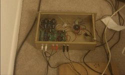
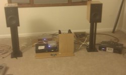
My working MOX!
After some time soldering, I finally have an active crossover! Very happy with it so far. Still testing it and need to finish the power supply, but it's operational.
Still learing how to use it too. It so versitile, that it's easy to get confused.
Vince
After some time soldering, I finally have an active crossover! Very happy with it so far. Still testing it and need to finish the power supply, but it's operational.
Still learing how to use it too. It so versitile, that it's easy to get confused.
Vince
Attachments
Can somebody send me a copy of the schematic for the original adjustable pcb from the groupuy
Thanks!
Thanks!
what happened to the analog Crossovers, has everyone moved over to using DSP's?
i thought this should still be a quality aproach for some aplications like extending a existing 2-way Speaker🙂
but i guess no reply in 2years 🙂
i thought this should still be a quality aproach for some aplications like extending a existing 2-way Speaker🙂
but i guess no reply in 2years 🙂
- Status
- Not open for further replies.
- Home
- Group Buys
- MOX-like crossover and discrete opamp group buy