Does anyone know why I am not able to adjust the gain on the MOX II multi-turn pots? Not one makes a change on the levels.
-Tried input thru aux1 and buffered input. No change.
-I'm not using the buffered outs.
-Using 10w single-ended on the tweeter and 65 watt a/b gain clone on woofer.
Maybe I'm not understand what "gain" is in respect to crossovers? Is it a bias adjustment? Is it possible the the output buffers are blown? The MOX does function.
Any suggestion would be helpful.
Thanks,
Vince
Of course, if you don't use the output buffer the attenuator is not in the circuit. You must use IC3 and take your output from BP/LP Out and HP Out. The buffered out near the input and IC1 is fixed.
Gain is what you'd expect, although in this case you only get attenuation at the end of the filter chain.
If you use 10K for R802 and R902 you will only have a maximum of 10 dB attenuation and won't be able to turn the signal off completely. If you leave R802 and R902 open nothing will happen when you adjust the pot. If you want more attenuation, reduce them to as little as 1K
Thanks BobEllis,
I used 25k pots because I couldn't find 22k. Do you think I should reduce this value for R801 & 901? I will try to reduce R802 & R902.
Thanks,
Vince
I used 25k pots because I couldn't find 22k. Do you think I should reduce this value for R801 & 901? I will try to reduce R802 & R902.
Thanks,
Vince
the attenuation at the outputs of the crossover are there to trim the signal to suit the amplifier gain and the speaker sensitivity differences between the low and high channels.
eg
Bass/Mid sensitivity 90dB/W @ 1m, power amp gain +28dB
Treble sensitivity 94dB/W @ 1m, power amp gain +26dB.
Feed the same voltage (let's call it +0dB) of signal to both and the SPL from the respective speakers are 118dB @1m and 120dB @ 1m.
The treble attenuation needs to be set to -2dB to correct for the gain and sensitivity differences. The quietest channel is set to zero attenuation.
-10dB attenuation should cover most installations. -20dB would be quite extreme and I suspect rarely if ever needed.
No need to reduce the value of the pots. If you use 10K for R802 and R902 you'll have 10.8 dB attenuation available. As Andrew pointed out, you won't often need more than that unless there are extreme mismatches in the driver sensitivities and/or amplifier gain. The idea of this arrangement is to allow the most precision of adjustment, not full range 0 to max adjustment.
Before changing anything, let's focus on making sure that you are connected properly so that you CAN adjust the gain. From where are you taking your output? The pads near IC3? A 10 db will sound like half volume or so. Are you sure that there is NO change?
Use a tone generator to feed a known signal into the board and measure the output. you can use a signal somewhere around your crossover point. Your DMM may not have flat response that high, so isn't good for accurately setting gains. We're just trying to verify operation. Adjust the associated pot and verify that the output voltage changes.
Which buffered output were you referring to in post 1? The two filtered outputs are buffered, and there is a full range buffered output.
Last edited:
Thanks AndrewT and BonEllis,
When you said there was 10db attenuation, I thought that if 2 drivers and amp combo have more than a spread of 10 db, it's a mis-match set of drivers or amps.
I won't change it. I'll try to use a smaller amp on the bass side. I have a 15w Aleph.
Might go better with the 10w Zen. I have 2 F5s, but one needs repairs and the other is on loan to a friend...for the past 1.5 years...maybe it's time he built his own. 🙂
Would you use a pink noise signal or try a pure tone at the mid point of the the driver's band? I have a tone generator and radio shack sound level meter. Or should I use a generator and AC volt meter at the XO's outs? I'm guessing the AC meter would be more exact. Would it have to be an RMS capable meter?
Thanks,
vince
you'll have 10.8 dB attenuation available. As Andrew pointed out, you won't often need more than that unless there are extreme mismatches in the driver sensitivities and/or amplifier gain.
When you said there was 10db attenuation, I thought that if 2 drivers and amp combo have more than a spread of 10 db, it's a mis-match set of drivers or amps.
I won't change it. I'll try to use a smaller amp on the bass side. I have a 15w Aleph.
Might go better with the 10w Zen. I have 2 F5s, but one needs repairs and the other is on loan to a friend...for the past 1.5 years...maybe it's time he built his own. 🙂
Would you use a pink noise signal or try a pure tone at the mid point of the the driver's band? I have a tone generator and radio shack sound level meter. Or should I use a generator and AC volt meter at the XO's outs? I'm guessing the AC meter would be more exact. Would it have to be an RMS capable meter?
Thanks,
vince
It's not the amp power we are concerned with here. You could use a kilowatt amp on the bass and a SET on the tweeter. What we are concerned with is the amp's voltage gain. If one amp has a voltage gain of 10 (20 dB like many Aleph's) and the other 23 (27 dB like an app note gainclone) and the driver sensitivities match, the signal to the higher gain amp must be attenuated 7 dB to make the driver outputs match. If your tweeter is 5 dB more sensitive than the woofer, you only need to attenuate the woofer 2 dB.
You can use pink noise or a pure tone. You don't need to connect your amps or speakers at this point, just measure the crossover signal with your ac voltmeter.
You can use pink noise or a pure tone. You don't need to connect your amps or speakers at this point, just measure the crossover signal with your ac voltmeter.
Last edited:
Before changing anything, let's focus on making sure that you are connected properly so that you CAN adjust the gain. From where are you taking your output? The pads near IC3? A 10 db will sound like half volume or so. Are you sure that there is NO change?
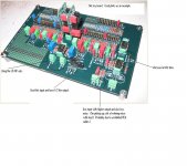
Here is an example photo of where the connections are made on the boards.
I'm using the outs near IC3. I have tried both aux1 in and + Gnd input near power input.
I have other ICs: NE5532, OP37 and OP2314. I can try different configs, if it will help. I think I used the OP2314 on the Hi-pass and NE5532 on the low-pass.
Also, to be more clear, I brought up the hi-pass pot and brought down low-pass. The hi-pass seemed a little brighter, but not much better. Maybe I am expecting more of a noticable change in gain that is just not available?
Attachments
Last edited:
When you use Aux1 input do you pull JP1?
A photo of YOUR board may help, but first do the measurements.
A photo of YOUR board may help, but first do the measurements.
I understand now.It's not the amp power we are concerned with here...What we are concerned with is the amp's voltage gain.
When you use Aux1 input do you pull JP1?
Yes, definitely do pull out JP1.
With the buffer, got better results with JP1>JP2>JP4>JP3*1. JP5 goes to HP out.
Will test tonight. At work right now.
Last edited:
The gain difference between the two inputs is that you probably have the input buffer set up with gain. Equal values for R1 and R2 will result in a voltage gain of 2.
When using Aux1 input try grounding In+ to see if that gets rid of the noise.
When using Aux1 input try grounding In+ to see if that gets rid of the noise.
When using Aux1 input try grounding In+ to see if that gets rid of the noise.
In other words, ground -In and +In when using Aux1. I will try it.
Thanks for all the help!
Vince
The {Zen} input impedance is 4.75 Kohms, and the gain is about 8.5 dB. This
means that the amplifier must be driven by an active source capable of
delivering 3.5 volts at 700 microamps.
If the GC is 27db, that's a 18.5db difference.
Both Dayton Audio drivers
The tweeter is 89db sens.
Woofer is about the same at around 87db (from memory).
The tweeter out would have to be turned up full and the woofer turned down full.
Yes, leave the HP running wide open and attenuate the signal to the low end. You'll need to reduce R802 and R902 to 1K to get there. With 25K pots you will have a little attenuation in reserve.
You can reduce the gain of the gainclone. The chip is stable down to gain of 10 (20 db). Changing the feedback network resistors to 10K and 1K will give you 20.8 dB gain, reducing the input attenuation requirement. Of course this might change the character of the amp.
Any luck verifying that you get some attenuation?
3.5Vac from a pre-amp is quite a lot from an opamp chip particularly when the load is <5k
I think you should look at a +6dB (or more) gain stage with high current capability tacked onto the HF output instead of the unity gain opamp.
I think you should look at a +6dB (or more) gain stage with high current capability tacked onto the HF output instead of the unity gain opamp.
Got Attenuation!
Just verified that there is attenuation. Almost 10db. I just didn't understand that it was a "fine adjustment". Now I get it! 😉
Best of all, now the left and right are balanced when connected to the rest of the system.
I won't to keep the gainclone in the system for long.
It's just easier to move around than a 45lb Aleph or F5.
I will need to learn how to determine input voltage gain for future use, but for now I have this thread for reference.
I think AndrewT outlined this in another thread I saw today.
Thanks for all your help Bob and everyone,
Vince
- Status
- Not open for further replies.
- Home
- Source & Line
- Analog Line Level
- MOX Active Crossover II Gain Adjustment