panomaniac said:
It sounds like the 501 has a speaker relay, so no turn on thump. Might be other stuff going on, too.
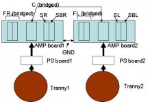
Yes, there's a relay for each chipset as can be seen in the pic I posted previously.
On the amp board there are pins labeled SPEAK-ON, PROTECT, and P-MUTE which all require +5v for the amp to be completely on. The brains of the moto power them on/off in a specific sequence.
I was initially concerned about how I would duplicate the power on/off sequence after I removed the amp. I found you can just power them all on/off at the same time. There isn't even the faintest hint of any on/off noise doing it this way.
Even if you yank the plug out of the wall while its powered up theres only a very small pop sound and then no power up noise at all when its plugged back in.
If any protection is tripped for whatever reason, you can just power down all three pins then power them back up.
Thanks theAnonymous1, I'm really glad the input caps helped the sound quality. I'm not quite ready to get started yet, but I'm excited about it now that I know it changed the sound for the better. I plan to modify all three receivers, and all 5 channels on each.
I unboxed moto #3 yesterday and it worked perfectly just like the other two.
I unboxed moto #3 yesterday and it worked perfectly just like the other two.
Thanks theAnonymous1! I guess you are having 60V, 1KW SMPS. What about 5V regulated and V10 supplies? Are they on the amp board?theAnonymous1 said:Yes, its all I have at the moment. I'm having some 1kw switching supplies built, but it could be quite some time before I actually get them.
How about converting the 5-ch pre-outs into 5-ch inputs going directly to the amp board?panomaniac said:
Ripping all that out and going directly to the power stage should really make a difference to the sound.
What about 5V regulated and V10 supplies? Are they on the amp board?
No, they are part of the main supply board. If you want to use a different supply you will also need to provide 5v, 10v referenced to VNN, and 24v for the relays.
How about converting the 5-ch pre-outs into 5-ch inputs going directly to the amp board?
Thats possible, although I'm not sure if the quality of the pre-outs is any better than the internal line levels.
abhi said:How about converting the 5-ch pre-outs into 5-ch inputs going directly to the amp board?
On a number of older amps, and just about the entire NAD line, the loop from preamp to power amp was on the back panel. So you could disconnect the loop there and use either part seperately. Very handy! You don't see that back panel loop much these days.
When you say "convert" the pre outs to inputs, I suppose you mean rewiring the RCA connectors to become inputs going directly to the power amp. A clever idea. 🙂
Might be a liitle tricky, as it's all printed circuit stuff, but worth a look.
Can the moto PS board still be used with SMPS? For example, remove the 10000uF caps, bridge and transformer and connect 60V SMPS to the PS board. The assumption here is all the secondary power supplies are DC-DC converters.theAnonymous1 said:
No, they are part of the main supply board. If you want to use a different supply you will also need to provide 5v, 10v referenced to VNN, and 24v for the relays.
Yes, Panomaniac. I meant to desolder all the wires going to 5-ch pre-outs and solder new wires from these pre-out terminals directly to the amp board. Will this scheme work without disconnecting the existing input connections to the amp board?panomaniac said:
When you say "convert" the pre outs to inputs, I suppose you mean rewiring the RCA connectors to become inputs going directly to the power amp. A clever idea. 🙂
Might be a liitle tricky, as it's all printed circuit stuff, but worth a look.
Can the moto PS board still be used with SMPS? For example, remove the 10000uF caps, bridge and transformer and connect 60V SMPS to the PS board. The assumption here is all the secondary power supplies are DC-DC converters
Unfortunately all of the supplies are powered by their own windings on the main transformer. If you wanted to use SMPS and still have the original supply for the other voltages, you would have to keep the huge toroid connected.
How about converting the 5-ch pre-outs into 5-ch inputs going directly to the amp board?
I misread that the first time. I thought you meant to use the signal coming from the pre-outs to feed the amp, not actually use them as inputs.
Don't the Pre-outs already go to the amp board internally? What would you be bypassing by connecting pre-outs directly to the amp signal input? If the oblect is to bypass all the "crap", isn't all the other signal processing upstream of the pre-outlets anyway? ie, won't the preouts output signal from the cablebox, DVD, Tuner, ect?
I kinda like the idea of connecting the spdif digital out of the dvd player to a single RCA on the back of the chassis connecting to an external DAC (with Vol control), and then connecting to the signal input of the amp. Makes the rest of the chassis useless....
I kinda like the idea of connecting the spdif digital out of the dvd player to a single RCA on the back of the chassis connecting to an external DAC (with Vol control), and then connecting to the signal input of the amp. Makes the rest of the chassis useless....
Hey John, there you are!
I've sent you two email in regards to the resistors. I got them in yesterday, I just need your addy and I'll send them out.
If anyone else needs any 20k resistors for the over-current mod mentioned earlier, drop me an email. I have a limited supply so first come first serve.
I've sent you two email in regards to the resistors. I got them in yesterday, I just need your addy and I'll send them out.
If anyone else needs any 20k resistors for the over-current mod mentioned earlier, drop me an email. I have a limited supply so first come first serve.
I made a very interesting discovery.
I was testing moto #3 out in the basement (it's sitting by moto #1) which is in the TV stand. Moto #3 sounded much less harsh compared to moto #1 using the both moto's DVD player. My first thought was that I had received a used moto. But then I thought let's try plugging moto #1 into the same wall outlet that moto #3 was plugged into. The outlets are about 8 feet apart. Bingo! Moto #1 now had a less harsh sound with a more pleasant deeper bass and had less noise maybe also.
It looks like cleaner/different outlets may have an effect on our moto's sound. I may finally go get a nice monster power strip to test the sound, with the T-amp also.
By the way this Power supply I got a couple of weeks ago is the best one yet I have used with the T-amp, and the Boomtube EX! If you get it you will have to splice in a connector pin that fits the T-amp, I used the heavy duty Boomtube EX's power plug.
http://www.allelectronics.com/cgi-bin/item/PS-1231/480/12_VDC_3.5_AMP_POWER_SUPPLY_.html
Tripath07 said:It looks like cleaner/different outlets may have an effect on our moto's sound.
You might want to have a look at this power filter.
NQN AC FIlter
I have not used it, but the engineering behind it looks solid. And there is enough info on the page that you could build your own, if you wanted to. Be CAREFULL. It's full AC, you know.
By the way this Power supply I got a couple of weeks ago is the best one yet I have used with the T-amp,
Yep, I've got a box full of those and really like them. They work well with the T-Amp. 🙂
panomaniac, thanks for the link to the power filter. It sure sounds better using that other outlet! I have a couple of questions regarding the input caps for the moto. theAnonymous1 used 4.7 uf caps, I also saw 2.2uf caps mentioned. What would the sound difference be between the two? Since there is no turn on thump with the moto using the 4.7uf caps is it a no brainer to go with them instead of the 2.2uf caps?
Last but not least what exact 4.7uf caps should I use? I could use a make and model number, and a link. I am now ready to buy a bunch of them and modify all three moto's.
Thanks in advance!
Last but not least what exact 4.7uf caps should I use? I could use a make and model number, and a link. I am now ready to buy a bunch of them and modify all three moto's.
Thanks in advance!
As for which size cap - I don't think you'd hear a difference, but I haven't tested it. And I don't know (yet) the input layout of the Moto.
There are kind of 3 schools of thought on the input caps.
1) All caps sound the same, just use a value much bigger than you need to be safe.
2) Caps all have their own sound. And since caps change the sound - why use more cap than you need?
3) Bigger is better because it will have the least influence in the pass band.
My guess is that any good cap between 1.5uF and 12uF will work just fine. And the big caps won't hurt because the relay eliminates the turn-on thump.
panomaniac, thanks for the help with the cap size, I'll probably go with the 4.7uf caps that theAnonymous1 used!
theAnonymous1, what is the name of the cap you used, and where can I buy them? Thanks.
Keep your fingers crossed for a miricle for Tripath. They are sooo close, check this new product out! It will be sold at Apple Stores, Circuit City, Target Stores, and many others, it goes on sale in September.
This product could be huge, I really hope Tripath survives!
http://www.mobilemag.com/content/100/337/C9214/
I think it may be the case of too little, too late for Tripath. With Garon gone, it seems hopeless. Too bad, such a good product. Good news is I think someone will buy them out...but I am hoping, and the stock has gone from under $.50 to $8 before.
I sold off 3/4 of my position in Tripath before Garon left and the stock tanked...
These chips may be rare and valuable someday...
I sold off 3/4 of my position in Tripath before Garon left and the stock tanked...
These chips may be rare and valuable someday...
Hey all, one more thing - is there a soft start on the power supply board somewhere? I would think at 600+ VA there would be one???
Finally I opened the unit up! On one side is a complex SMPS (used to power everything EXCEPT the AMP section). The AMP's supply seems to be in the bottom below 2 layers of PCBs (DSP/Decoder board and pre-amp board) 🙁 . theAnonymous1, how did you take apart the PS and AMP board?
The SMPS (which is used to power the other circuits) generates +-30V, +-5V and few other voltages. If the amp board is taken apart and rehoused, can this same SMPS be tweaked to power the amp section?😕
The SMPS (which is used to power the other circuits) generates +-30V, +-5V and few other voltages. If the amp board is taken apart and rehoused, can this same SMPS be tweaked to power the amp section?😕
- Home
- Amplifiers
- Class D
- motorola dcp501