Some pics attached.
Anything jump out at anyone?
Anything jump out at anyone?
Attachments
-
 297CED03-045D-41BC-BEA6-8F6A79C84F16.jpeg117.6 KB · Views: 170
 -
 EE7B4A30-2E01-4C2C-BA9F-2E1BA83D2129.jpeg113.1 KB · Views: 170
 -
 7BB0D906-3749-4E4A-B732-089D25878D92.jpeg122.3 KB · Views: 157
 -
 7D61AAB0-A38B-4FB8-AB71-15CF3410BD8F.jpeg102 KB · Views: 161
 -
 40466BEC-FAC1-4EF1-B064-963CC3DBF616.jpeg110.2 KB · Views: 150
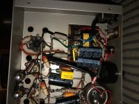
I’ve just had a quick poke around and found a loose solder joint on the positive banana connection. Thats not a good start!
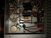
As it appears to still have the old carbon composition resistors in place you should check the value of every one of them.
Pictures aren't clear, but it seems to me that the ground terminal of the new filter capacitors has been relocated on the main ground bus wire, and this wire is ultimetely connected to the painted chassis with a screw. This remind me a issue were I got a intermittent motorboating on a freshly recapped amplifier. I traced the fault to a bad connection between the negative terminal of the new main filter capacitor and the chassis, due to the paint and oxide between the terminal lug I used as new anchoring point and the chassis. I now try to ground new capacitors on the same spot of the old ones (a bad ground choice may be a hum source) and I check the resistence between the chassis and the circuit ground. According to your picture, one of the old capacitors has been left connected to the circuit. I do the same on collector items that may be turned on shortly once in a while (if ever), to keep authenticity, but I usually do a full capacitor replacement on devices of this age that will be used daily.
EDIT: I just cheched the MA12 assembly and operation manual, and there are NO 33uF capacitors listed on the part list. The new capacitors I see in the picture seems to be 33uF capacitors (all of them). Component substitution could lead to issues.
EDIT: I just cheched the MA12 assembly and operation manual, and there are NO 33uF capacitors listed on the part list. The new capacitors I see in the picture seems to be 33uF capacitors (all of them). Component substitution could lead to issues.
Last edited:
As it appears to still have the old carbon composition resistors in place you should check the value of every one of them.
A resistor has been changed, so they have been checked, I presume. But I wonder what value the output tubes cathode capacitors may have now, since they are still the original ones.
full schematic
I would make sure to check if C1 and C2 decoupling caps are faulty.
And make sure to add a high value input grid resistor to ground in case the volume control (R1) wiper lose contact.

I would make sure to check if C1 and C2 decoupling caps are faulty.
And make sure to add a high value input grid resistor to ground in case the volume control (R1) wiper lose contact.
Anything jump out at anyone?
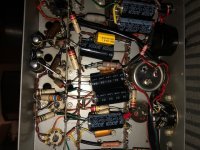
1: as pcan points out, the EL84 cathode bypass caps (C10 + C11) are the original Plessy ones. They have a poor reputation and should be replaced. They are likely open circuit...
2: pcan again spotted the electrolytic caps are low in value compared to the originals, they were 60+250uF (C1) and 50+50uF (C2). They are grounded near their original points though. I think the connection to the original cap is just a tag point now, the black ground is not connected and the can is insulated.
Then, C3, the 510pF cap, looks like it is a Dubilier 'domino' cap. These can fail randomly, it would be worth a careful check.
And strangely the wire to the red socket (3 ohms) is red. This is normally yellow. Has the output transformer been changed?
Yes, the output transformer on the faulty amp is not original.
Something has just occured to me, I have assumed all along that the 15ohm tap was redundant, owing to the fact that the new banana plugs were fitted. When testing the amps I have been using an old set of Wharfedale W4 speakers that are 15ohms! I have just hooked the amps up to the speakers using the 15ohm tap and cannot hear the motorboating.......
Could it be something as simple as that, the 15ohm speakers over driving one of the amps?
Could it be something as simple as that, the 15ohm speakers over driving one of the amps?
Why didn't you tell us that the faulty amp had a different OPT? Different OPT means different LF response which can mean different LF stability. If you want to use them as a stereo pair then they need to be identical, so both OPTs need to be changed unless you can find an exact replacement for the original.
As others have pointed out, capacitor values have been changed which will affect LF stability. Maybe you need to find a better technician?
As others have pointed out, capacitor values have been changed which will affect LF stability. Maybe you need to find a better technician?
- Home
- Amplifiers
- Tubes / Valves
- Motor Boating Caused by SS Preamp. Help!?