Good morning Gentlemen!
I'm trying to develop a test chamber with a very high level internal acoustic environment (140 dB, 2Hz - 8KHz) and can't seem to locate a midrange driver that can survive it. Right now I have eight Pyle Pro PBD832 mounted to provide the range from 300 Hz up . . . and they lasted exactly 5 seconds at 138 dB.
The Pyles were under power at 225 watts (they're rated at 1000, but the amp can only develop 225), so I don't think I'm electrically heating them to destruction.
I have an extra Pyle and just took it apart to see what was inside and found a very lightly made plastic voice coil/diaphragm structure with what looks like brass tabs to bring power in. The slot that the voice coil is normally in was filled with some sort of brown oil, and if I didn't know this was a new driver I would have thought the thing was burned up, but it must be some sort of ferromagnetic damping liquid.
I think what is happening is that the acoustic energy from the low frequency drivers (4 Kicker Solo18, driven at 14,000 watts each in a 60 cubic foot chamber) is backing up the horns and ripping up the voice-coil assemblies in the Pyles.
At this point I'm pretty much limited to some driver with a 4 hole bolt pattern on a 4" circle.
Does anyone have any thoughts? Know any really rugged drivers?
Thanks!
BillyDoc
How about the BMS 4592ND-MID? It's right pricey, for sure, but will it take some abuse? Does anyone have experience with it?
How about the stuff made for public address, like the EV, Atlas, Dayton, MCM, etc. They are made for mids and are rugged. They don't go much above 8KHz, tho. Generally they use phenolic diaphragms.
They are screw, but adapters are not expensive.
They are screw, but adapters are not expensive.
what is the purpose of this??
Making hamster ears bleed??
Getting 140dB even nearfield is a non trivial exercise. Figure out the power handling of the driver & the sensitivity and then add in the power required to make the requisite power levels and you will quickly see the problem.
If you look online you can find some solutions to this problem that were used for very very narrow bandwidths in LOUD environments (aircraft carriers for example). They look like V-12 race engine intake manifolds. Anyhow at one time I ran across some things about this - and saw a cool piece on ebay at one time made for the military...
I doubt that any of these standard issue consumer compression drivers will permit you to reach 140dB, even in a closed box... even an array of them, maybe with a sufficient number... then you have some issues with interference... but...
So what is this for??
_-_-bear
PS. if you clip the amp, you will quickly destroy most drivers at that level... and NO WAY is that Pyle compression driver rated at 250watts... much less 1000. Something wrong with that picture.
PPS. Ok I looked it up - they DO rate it for 500watts RMS... seems impossible to me. Ferrofluid or not.
Last edited:
And they are only rated from 800 Hz up... derate as you go below that frequency by a lot, assuming the diaphragm can physically do it (unlikely)...
Community Light & Sound used to make an 8" diameter diaphragm midrange compression driver....
Also, what sort of horn did you try to use to make 300Hz?? How did you load these drivers??
Community Light & Sound used to make an 8" diameter diaphragm midrange compression driver....
Also, what sort of horn did you try to use to make 300Hz?? How did you load these drivers??
Hi bear,
Only modest amounts of blood have been lost so far, mine during construction! But I'm happy to report that we did succeed in achieving 140 dB with a flat spectrum from 4Hz to 8KHz for six seconds. After about five runs the mids all got very quiet, however. We also have very good control of that spectrum, down to third octaves.
The purpose is a "Noise Stress Test Chamber" to be used to stress-test equipment that is deployed near a rocket launch. At about 50 feet the noise level is over 160 dB, but the top 20 dB can be eliminated with sturdy cabinetry, leaving the internal equipment at the lower sound level. The six seconds is because the rocket should be gone by the end of that time. If it isn't the noise level is often way higher, for a brief period. A big "boom" in other words.
I think the voice coil assemblies are going to be "consumables" for this machine.
BillyDoc
You're welcome! They may not be what you need, but at least it's worth a look. Remember, most of them are for 70V systems, so you'll have to bypass the 70V transformer.
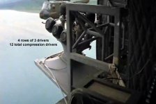
You may find that nothing will stand up to your use. Back in the old days, they used to build manifolds and use 2 or more drivers to achieve higher spl with compression drivers. Take a close look at the speakers hanging off the choppers in Apocalypse Now. They are using 12 drivers on a single horn! (like Bear's V-12)
You may find that nothing will stand up to your use. Back in the old days, they used to build manifolds and use 2 or more drivers to achieve higher spl with compression drivers. Take a close look at the speakers hanging off the choppers in Apocalypse Now. They are using 12 drivers on a single horn! (like Bear's V-12)
Attachments
Thinking about your insane rocket launch levels, you may be on to something with the bass coming back up the horns to destroy the diaphragms.
We need to get GM onto this thread, he has built some super loud warning horns.
We need to get GM onto this thread, he has built some super loud warning horns.
bear,
I missed your question about what horn, they were all Selenium HL14-50 2" Exponential Horns, 45x45 4-Bolt.
I'm still looking for PA drivers, the best I've found so far is a MCM rated at 100 watts. Which has me thinking about a manifold, panomanic. I do have a space problem though.
BillyDoc
I missed your question about what horn, they were all Selenium HL14-50 2" Exponential Horns, 45x45 4-Bolt.
I'm still looking for PA drivers, the best I've found so far is a MCM rated at 100 watts. Which has me thinking about a manifold, panomanic. I do have a space problem though.
BillyDoc
Last edited:
Hmmm... the Hl15-50 is a fat, short horn. Did you choose it for cost, space or some other reason?
The Selenium HL14-25 is also cheap and would fit the MCM screw drivers. Instead of a manifold, maybe a bunch of those?
But really getting a horn that will work from 300Hz up means a big horn. Like a mouth 24" wide. My Altec 300Hz horns are 30" wide. But they will actually play lower. That is going to be part of your problem, most compression drivers are not made to play that low without damage.
How steep is your crossover?
If it's a closed chamber, could you replace the air with something more suitable?
Not sure how low you could get output but you could use lots of piezo elements as they are less sensitive to LF damage.
It's probably not worth it with a horn if you can cover one wall with elements.
No experience with piezo though.
If you need to fill in 300Hz+ you could maybe make your own driver. Maybe with a moving magnet allowing the VC to be cooled. Or using two coils. Active cooling is possible here. A metallic dish with the middle flexing maybe.
Or the middle could be fixed with the outer edge moving. If you hit resonance lots of fun can be had.
Probably not that high in bandwidth though.
Do you require music to be playable or is if fine if it sounds like crap?
Last edited:
panomaniac, I have serious space problems! The chamber is 44" in diameter with elliptical ends about 6 feet apart, like a big propane cylinder on it's side. On one end are two 6' dia elliptical ends clamshelled together to form the backside area for the speakers. It's all made out of 3/8" stainless steel. All eight horns are in four groups of two in a circle around the woofers in the middle. I would post a picture if I knew how. On the backside of the horns I only have room for 8" dia drivers, and it's hell to get to the bolts because you can't get your head in there to align anything. Oh, and the crossover slope is 18 dB/octave.
The system worked very well . . . until it died. Which I suppose is a design flaw. There was only 95 dB at one meter from the door when it was running at 140 dB inside.
David . . . it sounds like crap. White noise, actually. The machine is on wheels, I thought about dB drag racing . . .
BillyDoc
The system worked very well . . . until it died. Which I suppose is a design flaw. There was only 95 dB at one meter from the door when it was running at 140 dB inside.
David . . . it sounds like crap. White noise, actually. The machine is on wheels, I thought about dB drag racing . . .
BillyDoc
OK, I have a basic picture. A few questions for you:
I'm just thinking that you might be able to use the drivers you have, if you can move the crossover point up. Because I seriously doubt the Pyle drivers on that horn are really giving you much output below 1KHz. So you have to push them even harder to get the SPL you need. That's going to fry them, as you found.
If you can shift the crossover point up and let the other drivers take some of the load between say 300Hz-1Khz, the compression drivers will have a much easier task. You likely won't have to throw so much power at them.
Make sense?
- You say you were putting 250W into the horns - and there are 8 horns and drivers? How are they wired? Series, parallel, combo?
- Would you be able to replace the horns with models meant for 1" throat screw-on drivers?
- Why the low crossover point? That may be the biggest part of your problem. Trying to drive the compression drivers at that power, that low and on that horn isn't working.
- Can you move the crossover point up an octave or 2?
I'm just thinking that you might be able to use the drivers you have, if you can move the crossover point up. Because I seriously doubt the Pyle drivers on that horn are really giving you much output below 1KHz. So you have to push them even harder to get the SPL you need. That's going to fry them, as you found.
If you can shift the crossover point up and let the other drivers take some of the load between say 300Hz-1Khz, the compression drivers will have a much easier task. You likely won't have to throw so much power at them.
Make sense?
This is a serious acoustics problem.
Not something that is likely to be solved by seat-of-the-pants solutions.
The pressures are substantial, and in a sealed chamber we have a special case.
There is no doubt in my mind that the LF energy will modulate the diaphragms of the horns...
It's entirely unclear to me from the description why it's in a small elliptical chamber to begin with...
This is a non-trivial problem to solve, especially if there are going to be multiple drivers running at different frequency ranges - and even if they are all at the same frequency, if there is more than a single entry to the chamber - problems.
Standing waves are going to be brutal...
You've got troubles, my friend...
_-_-bear
And yet it worked, if ever so briefly. It may be as simple as a move up in crossover frequency. We need to know more about that part.
Well... more like one that rises a few meters then tumbles back down. You've seen the footage. 😉
Good morning everyone!
panomaniac, each group of two drivers (8 ohms each) is wired in parallel and powered by one channel of a Fender amp rated at 450 watts/channel, so 225 watts per driver. I could go with the 1" screw on if I had to do it. The low crossover is mostly to protect the subwoofers, which it seems to have done. I also have forced air over the voice coils in the subwoofers. So I would rather not move that crossover point, it's already too high for the subs.
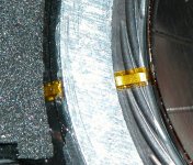
I have some more info this morning though. I put the new PDB832 voice coil under a microscope and discovered that the leads to the voice coil are not brass after all, they are bits of flexible circuit board (mylar?) with brass deposited or etched, or maybe gold plated copper. The end of this ribbon away from the voice coil passes under an aluminum ring and is glued down rigidly. Then about a quarter inch of ribbon lies across the flexible part of the diaphragm and is soldered to the voice coil. The flexible area is made flexible by embossing a series of raised areas that lie, not on a circumference but spiraling inward. So, as the dome moves in and out a slight rotation will be imposed about its central axis. Most interesting, the conductor ribbon appears taut lying across these embossed features. So when an external pressure comes up the horn and drives the dome this ribbon has a very limited range with which to accommodate the movement. I think this was the problem.
I'll attach a picture.
BillyDoc
panomaniac, each group of two drivers (8 ohms each) is wired in parallel and powered by one channel of a Fender amp rated at 450 watts/channel, so 225 watts per driver. I could go with the 1" screw on if I had to do it. The low crossover is mostly to protect the subwoofers, which it seems to have done. I also have forced air over the voice coils in the subwoofers. So I would rather not move that crossover point, it's already too high for the subs.
I have some more info this morning though. I put the new PDB832 voice coil under a microscope and discovered that the leads to the voice coil are not brass after all, they are bits of flexible circuit board (mylar?) with brass deposited or etched, or maybe gold plated copper. The end of this ribbon away from the voice coil passes under an aluminum ring and is glued down rigidly. Then about a quarter inch of ribbon lies across the flexible part of the diaphragm and is soldered to the voice coil. The flexible area is made flexible by embossing a series of raised areas that lie, not on a circumference but spiraling inward. So, as the dome moves in and out a slight rotation will be imposed about its central axis. Most interesting, the conductor ribbon appears taut lying across these embossed features. So when an external pressure comes up the horn and drives the dome this ribbon has a very limited range with which to accommodate the movement. I think this was the problem.
I'll attach a picture.
BillyDoc
Attachments
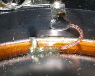
Here's a picture of the connection on a different compression driver, one that was in a piece of equipment that was also used for high-level noise testing since 1995 and survived the experience nicely.
This one had room to move when that external stuff came up the horn!
This one had room to move when that external stuff came up the horn!
Attachments
- Status
- Not open for further replies.
- Home
- Design & Build
- Parts
- Most rugged midrange compression driver