This thread is about my wish to change the sound character in the Balanced Line Stage (BLS) through different Mosfets and Different amounts of BIAS
I built a balanced line stage preamp, and borrowed it to a friend, who is very fond of it, and want me to build one for him. But, he feels that the it is a little "thin" sometimes, best heard on male vocals.
The quest for me now, is to try and change the sound towards the "warmer" or "thicker" - which I don’t think can be achieved with changing the output capacitor - the component I always hear people rave about. Nelson himself says that people never sends him new transistors, even though these components tributes the most to the changes in sound.
I then came to think about my experience with my Zen 4, where I have used two different types of mosfets with two different BIAS levels.
My understanding of the changes in sound, was that the more BIAS, the more the sound tended to go towards a change in the tonal balance - the sound got "beefed" up, and instruments sounded fatter in the lower tonal structure. Also, i noticed that the perception of space widened, so a room would seem larger - it was as if the walls was kicked farther away.....
These changes was for a single ended configuration, and I’m not sure if the same changes would be seen when more transistors are placed in parallel - but the BLS that I seek to change is also single ended.
So - I want to up the BIAS in the BLS, and properly use some other
transistors - 510, 520, 530, 620, 630 and so on. I notice that the lower end in my power amp got better with larger devices (speaking of current handling) and the same time the highs got less pronounced. I don’t know if this can be transferred to a line stage ?? Has anyone build the BLS with different transistors, and what was the difference in sound ??
The question for me is – how much can I allow my self to raise the BIAS – to the extent that I have excessive heat on the mosfets, or my PSU runs out of power?
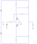
I suspect that I should change the resistor value in the current source – which is 1500 ohms(two 750 ohm I series) and going from the negative supply to source, and has a voltage drop of 56 volts. I get (56/1500)= 0,0373 amps, which is 2 watts of power dispatched. Is this the transistor value I should lower if I want a higher BIAS on the devices ? Or, is it the load transistors (750 ohms) going from positive supply to the drains ?
Any suggestions ??
Cheers !
Hans
I built a balanced line stage preamp, and borrowed it to a friend, who is very fond of it, and want me to build one for him. But, he feels that the it is a little "thin" sometimes, best heard on male vocals.
The quest for me now, is to try and change the sound towards the "warmer" or "thicker" - which I don’t think can be achieved with changing the output capacitor - the component I always hear people rave about. Nelson himself says that people never sends him new transistors, even though these components tributes the most to the changes in sound.
I then came to think about my experience with my Zen 4, where I have used two different types of mosfets with two different BIAS levels.
My understanding of the changes in sound, was that the more BIAS, the more the sound tended to go towards a change in the tonal balance - the sound got "beefed" up, and instruments sounded fatter in the lower tonal structure. Also, i noticed that the perception of space widened, so a room would seem larger - it was as if the walls was kicked farther away.....
These changes was for a single ended configuration, and I’m not sure if the same changes would be seen when more transistors are placed in parallel - but the BLS that I seek to change is also single ended.
So - I want to up the BIAS in the BLS, and properly use some other
transistors - 510, 520, 530, 620, 630 and so on. I notice that the lower end in my power amp got better with larger devices (speaking of current handling) and the same time the highs got less pronounced. I don’t know if this can be transferred to a line stage ?? Has anyone build the BLS with different transistors, and what was the difference in sound ??
The question for me is – how much can I allow my self to raise the BIAS – to the extent that I have excessive heat on the mosfets, or my PSU runs out of power?
I suspect that I should change the resistor value in the current source – which is 1500 ohms(two 750 ohm I series) and going from the negative supply to source, and has a voltage drop of 56 volts. I get (56/1500)= 0,0373 amps, which is 2 watts of power dispatched. Is this the transistor value I should lower if I want a higher BIAS on the devices ? Or, is it the load transistors (750 ohms) going from positive supply to the drains ?
Any suggestions ??
Cheers !
Hans
Attachments
Buhl,
First of all, give us details of the mosfet's, resistors and output caps used
in your Bosoz.
Then I think you will get a lot of advises to Upgrade!!
I have built 3 Bosoz / CCS-X-Bosoz Prototypes with
International Rectifiers IRF610 {tried IRF 520 also} the IRF610 are the best for the job!
35 to 45 mA bias ; Higher the bias better the result.
Output cap's BlackGates N types 2*10microF
Drain resistors Panasonic 3 watts, I don't think there is much to gain here...
Then, read the X2 owner's manual and perhaps go for 80/90 volts...
http://www.passlabs.com/downloads.htm
Regards.
PS: I often listen to : Florent Pagny "Baryton" last CD and I don't
think my preamp lacks on male voices.
http://florentpagny.artistes.universalmusic.fr/
Alain.
On this particular circuit, the bias will have an influence, but also
the resistance between the Sources which sets the internal
gain. On the Aleph P (see Aleph P service manual at
www.passlabs.com ) this could be set on the front panel with
a knob, and varied from 200 to 2.2K ohm. Most users liked the
sound best at about 500 ohms or so, but using a pot allows you
to trim it to taste.
😎
I'm in a hurry, but thought I'd drop in a couple of ideas:
--Yes, output caps can make a big difference in the sound. The line stage I've been working on started with the Panasonic 10uF 100V metallized polyester caps from Digikey. The bass was fairly good, but the mids and highs left something to be desired. I've been experimenting with different caps and am currently pretty pleased with the WIMA FKP-10 metallized polypropylene bypassed with a small polystyrene. I'm having trouble finding larger values here in the US, but you may have better luck. If you really want to drop money, you can try the boutique caps like the RelCap/MIT and things along those lines, but the caps can easily end up costing as much as all the other components combined. I won't defend their pricing structure, but they do sound very good, indeed. On a dollar/performance ratio, the FKP-10s rate highly.
--Increasing the bias will make it sound warmer. Increase the bias, but watch the device limits.
--As you go to larger and larger current devices, the capacitance of the device will increase. This will, to some extent, darken the sound. So, yes, by all means try different devices.
--More feedback tends to make a circuit sound thinner. Conversely, less feedback sounds fuller, but with less 'hi-fi' detail. If your friend wants a warmer sound, you could reduce the feedback (which has other benefits as well, although the distortion will increase somewhat).
All these things--and more--go into voicing the final circuit. Balancing all of them can lead one to drink.
Follow me. I won't let you die of thirst.
Grey
I have tried with IRF510, 610 and 620,
with the same Mark Knoffler’s voices.
Nelson Pass says the higher drain voltage works better.
People say the higher bias results in better.
Meanwhile, I have tried to reduce the drain voltage,
the bias, and the amp gain as acceptably low as possible.
And no feedback resistor to the input . . .
My latest end is with IRF620,
+/-30 rail voltages and 30mA bias/FET.
I have CCS . . .
The amp gain is about unity at full volume.
With! these! I! am! satisfied!
My output coupling cap is 220uF(elect)//0.22uF(Chinese MKP film) . . .
Chinese MKP film has tried to make me disappointed slightly,
but one week later, all have turned out ok . . .
Regards
jH
Originally posted by Buhl I suspect that I should change the resistor value in the current source – which is 1500 ohms(two 750 ohm I series) and going from the negative supply to source, and has a voltage drop of 56 volts. I get (56/1500)= 0,0373 amps, which is 2 watts of power dispatched. Is this the transistor value I should lower if I want a higher BIAS on the devices ? Or, is it the load transistors (750 ohms) going from positive supply to the drains ?
Any suggestions ??
Cheers !
Hans [/B]
HI,
to change the bias just change the resistors from source to neg supply. Bias is always 56/R with a -60V supply. Depending on the bias change you´ll have to change the upper resistors too otherwise you will loose some output swing but this is not so critical (just keep the dc value between 20 and 30 volts.
William
First - thank you all for answering my thread - its priceless to have comments from such skilled persons !....
Alain: my BLS is build with standard components - carbon resistors for load and bias, and metal film for signal. IRF 610 Fets, one PSU @ +/- 60 volts - output caps are 10uF bipolar bypassed with 0,22 uF ERO / Vishay film cap.
I wil try to insert a potmeter between the mosfets sources as nelson also described in the original article.
Grey: its good to hear that output caps not only affects the higher region of the sound spectre - I always hear of different capacitors effects on treble and room. Have read several places that electrolytics can be a good choice when large values are needed - as jh6you is using. I have some Elna Cerafines and Panasonic MUSE I will try soon.
How do you reduce the amount of feed back ?? I would expect a resistor going from drain to gate, bu only see the 100K that load the input/output ???
Im not afraid of introducing distortion i order to taylor the sound - I suspect thats what jh6you achieves when lowering the rail voltages, if I recall the original article ??
I will also try to lower the Bias resistors to 1100 ohms, giving 50 mA of Bias......
Thanks to all for helping me out !!
Cheers !
Hans
Mr. Pass,
With your "sound viewing device" (how do I write this?), like Audio Precission or FFT, what is the difference between one bias value and higher / lower one? Is the 2nd harmonic or other harmonic differs (so the sound is heard as "thicker" or "warmer")?
With your "sound viewing device" (how do I write this?), like Audio Precission or FFT, what is the difference between one bias value and higher / lower one? Is the 2nd harmonic or other harmonic differs (so the sound is heard as "thicker" or "warmer")?
Electrolytics a good choice? Never. However, there are times when they are a necessary choice, simply because you need too much capacitance in the circuit for any other kind of cap to be practical. With luck, some clever young lad or lass will come up with another type of cap that doesn't have the problems that electrolytics have.
But I'm not holding my breath.
Grey
But I'm not holding my breath.
Grey
lumanauw said:what is the difference between one bias value and higher / lower one?
In the range that we deal with on Mosfets, as you increase
the bias the gain goes up slightly, but the distortion declines
a lot. Also the distortion will cluster more around 2nd and/or
3rd harmonics instead of higher order.
GRollins said:Electrolytics a good choice? Never. However, there are times when they are a necessary choice, simply because you need too much capacitance in the circuit for any other kind of cap to be practical.
I'm not too religious about capacitors - gain devices and the
occasional transformer are much larger sources of trouble.
There's a right cap for the job, and as you get above 10 uF,
electrolytics start looking attractive. 😎
Your comments on caps are essentially the same reasoning that led me to experimenting with caps instead of such 'obvious' solutions as level shifters.
Removing all caps from the signal path is a noble thing...yet I'm getting better results at the moment by removing gain devices. Obviously, there's a limit to how far you can take this, but it does lead you into a mindset where you question things that others take for granted.
Too many people refuse to ask questions. Where is the question authority attitude that was so prevalent thirty or forty years ago? It's always appropriate to recheck your assumptions once in a while.
Grey
Just thought I'd throw in my two cents on the output caps. I currently have 10uF Solen metallized polyrpopylene film caps in my BZLS variant. They aren't horrifically expensive, in fact quite reasonable, and to my ear they are a big improvement over the electrolytics. Their main drawback is fitting their size into your circuit.
Cheers,
Terry
Cheers,
Terry
...yet I'm getting better results at the moment by removing gain devices
I had experiment data that concluded the same thing. But later it turns out it is not "using minimal gain device/transistor" but rather "using minimal signal feeded to base/gate". It is quite different between these 2. I think this is because the relation of magnification between base with emitor/collector is not linear. So try to advoid as many as non linear behavior in any point.
I experimented that using transistors like in common base configuration does a lot less of harm to the sound. Like folded cascode for example. Just try to minimize the signal feeded to base/gate (and picked up at Emitors/Collectors/Drain/Source).
It is difficult to implement this principle. For instance, up until now I cannot figure what configuration that doesn't inject signal to base but does a function of a simple differential (can control all the fixed gain value and can control DC offset) with common base transistors (using 2 transitors max)
There is a simple but "very beautiful" solution provided by NP. He used to call it "close reationship"
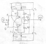
For example, you look at the schematic of "thresholdstatis2-3schem". If you look at around bias generator, you will find 2 Resistors with value of 4k7(with arrows pointed at them).
For days (or weeks) I try to figure out what are they doing there. And they do gives different audible sound (although they are only 2 resistors of the whole amp).
Then I remember a post when NP commented on a configuration used by John Curl (NP doesn't know the configuration is taken from a design that JC uses). He uses words "close relationship" in that post.
Then I "think" I know what are the 4k7's doing there. It gives "close relationship" between VAS and output node. It's like the VAS is directly driving the output node, with help of current magnification of the final stage.
While we cannot make all audio signal not going to any base/gate, this approach by NP gives similiar sound result.
Threshold schematic(s) are really wonderfull. It contains many-many beautiful things inside them. But why they have less discussions than they deserve?
Have you considered a 'current feedback' input stage in inverting mode? It won't have as good a DC performance as a LTP, but it can be good enough. As few as one transistors, but a symmetrical one with two transistors will have lower DC offset.lumanauw said:...what configuration that doesn't inject signal to base but does a function of a simple differential (can control all the fixed gain value and can control DC offset) with common base transistors (using 2 transitors max)...
Hi, JH,
Yes, you are right. Usually it is referred to 2nd stage of the 3 stages amp.
Mr.Evil,
Yes, the "current feedback" configuration (where the feedback is taken to emitors) is exactly have the same properties that I pursue. But it still inject the signal to base. Do you have configuation that feedback and signal input none is going to base?
About "close relationship". In bootstrapped VAS (old fashioned VAS) it usually sounds better than modern designs (with current source). Bootstrapped has Capacitor connected to output stage. So, in bootstrapped VAS, the VAS is "closely related AC'ly" to the output stage, that's why it sounds different than CCS VAS.
Yep. In inverting mode the bases/gates are grounded and both input and feedback goes to the emitters/sources, as per the attachment.lumanauw said:...Yes, the "current feedback" configuration (where the feedback is taken to emitors) is exactly have the same properties that I pursue. But it still inject the signal to base. Do you have configuation that feedback and signal input none is going to base?..
Attachments
Hi, Mr.Evil,
Thanks for the idea. How to implement your idea, if the front end is not JFET (Bipolars for instance) without adding complexity?
I've got my own version of "none signal going to base" by marrying NP's smart bias with Jim Strickland's Transnova.
But I still feel this will burden the preamp, cause the "inverted differential" will need quite some current to drive it.
Attachments

- Status
- Not open for further replies.
- Home
- Amplifiers
- Pass Labs
- Mosfets and BIAS - sound design...