I have it done with IRFP's. I just did exactly as it was stated on the project page. I did my own pcb which was not fully describe on the project page.
The IRFP240/9240 really arent as bad as some people make out.
Despite them being switching MOSFETs they work very well in audio.
Its amazing what feedback can turn an unlinear transistor into.
Oh sorry, I did not use ammeter to calibrate, as I had said in earlier post. I never change anything from the original design for any of my projects (except the pcbs where I did my own, maybe with a few modification). I am no good at these so I did what the designer said and so far I had not failed in any of them (almost 10 now).
Schematic was the one on redciruit page100. No change, no monkey business.
Schematic was the one on redciruit page100. No change, no monkey business.
Hi Brian
You say this 'Mosfet Amplifier' is for a school project. This makes it sound like you intend to build this project as a demonstration of a Mosfet amplifier for audio, which assumes a learning experience. You would need to know how such a circuit, and more specifically mosfet transistors work in order to explain the presentation, no? If you have the time, you should study how mosfets work, transconductance (Gm) vs Id (with respect to BJTs, Gm vs Ic), internal parasitic reactive components (that can create instabilities and how to stabilize them), the non-linear junction capacitances, ect., and the difference between Lateral and Vertical types of mosfets. They have different properties, some good some bad. They were designed with different intentions. Everything in electronics is a trade-off. A circuit designed to use the Lateral type is not going to work very well with the Vertical type. It may work, but Hi-Fi is a far stretch of how well it will work, if at all. There are inherent issues with Vertical types (after all they are designed to be used as switches🙄 ) that have to be addressed if you intend to use them in the 'linear' region. It is obvious the designer for that ‘Red Circuit’ project has no idea what makes Verticals different from Lateral mosfets. This is not to say that a Hi-Fi amp can't be made from Vertical mosfets, it most certainly can be....🙂
If your intent is to just get it to work in order to show generally how an audio amp works, then continue to try it with a large heat sink and very low bias. But don't forget the gate to source protection Zeners.
BTW, FB certainly does not ‘fix’ everything, this idea is perpetrated by those who usually use it improperly or rely on it to ‘fix everything'🙄, giving the whole idea of feedback a bad rep..............
”I don’t know where the instability and high frequency distortion components are coming from so I’ll just compensate the crap out of the circuit until the level is acceptable.” .....
Uh huh……
This circuit is designed to use Lateral type mosfets and could work quite well with them. You still need to include the gate to source protection Zeners.
To use Vertical type switching mosfets properly and without issues, there has to be some major re-design of the circuit. I suggest to stick with the Lateral components as this will simplify the circuit and improve the quality of your presentation greatly. Of course they may be more expensive, but that is a trade-off you typically run into in electronics.😛
I can recommend some reading material if you're interested.
Last edited:
:Yes, it's a project for school. Everything was new for me. I've learned how bi-polars can work as an amplifier, but only learned to use MOSFETS as a switch.
I still have a pair of IRFP right here, I'm going to rebuild the PCB in two parts 1: long-tailed-pair+current mirror. The second part will be the amplifier itself.
If it still doens't work I'll have to take some of my pocket money and buy laterals 🙄
Thanks
I still have a pair of IRFP right here, I'm going to rebuild the PCB in two parts 1: long-tailed-pair+current mirror. The second part will be the amplifier itself.
If it still doens't work I'll have to take some of my pocket money and buy laterals 🙄
Thanks
Don't know why you keep saying that we need to modify the circuit to use V-fets. I had 2 pcs working as shown exactly in page100 of redcircuit. In fact they are playing while I am writing this email. The heatsinks are not even warm today as ambient here is only 18C. Let me declare it once and for all : this circuit is good using V-FETS, it may work with laterals (I don't know and I won't try) but that is way too expensive.
Brian,
Just do exactly as the instruction and be careful not to make mistakes of your own and you will have it done. Don't make things complicate when you don't have to. The only thing I had changed is to use MPSA42 instead of MPSA43 becuse I have a handful of MPSA42 at hand while the 43 is obseleting and I did ask the designer for advice on that. The only problem I had was I drawn the pcb slightly wrong because I did not check the pin for the 546 and the 43 and I had the 546 just like the 43. But I was lucky enough to had noticed it before I solder it. So no problem with that.
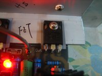
Hope the photos can convience you. Keep your money for something else. Vfets are good enough for this. And if you want to use Lfets, ask the original designer for an opion first before you flush you pocket to the toilet.
Brian,
Just do exactly as the instruction and be careful not to make mistakes of your own and you will have it done. Don't make things complicate when you don't have to. The only thing I had changed is to use MPSA42 instead of MPSA43 becuse I have a handful of MPSA42 at hand while the 43 is obseleting and I did ask the designer for advice on that. The only problem I had was I drawn the pcb slightly wrong because I did not check the pin for the 546 and the 43 and I had the 546 just like the 43. But I was lucky enough to had noticed it before I solder it. So no problem with that.
Hope the photos can convience you. Keep your money for something else. Vfets are good enough for this. And if you want to use Lfets, ask the original designer for an opion first before you flush you pocket to the toilet.
Attachments


I want to thank you all, the amp is working right now. No problems and it runs really cool.
It's sound a bit sharp (vocals) but that's MOSFET sound isn't it?
And what bigpanda said is right, circuit runs perfectly with V-fets.
Just keep it from heating up too much, this wil cause a thermal runaway.
Nice project for beginners!
It's sound a bit sharp (vocals) but that's MOSFET sound isn't it?
And what bigpanda said is right, circuit runs perfectly with V-fets.
Just keep it from heating up too much, this wil cause a thermal runaway.
Nice project for beginners!
Last edited:
It's sound a bit sharp (vocals) but that's MOSFET sound isn't it?
And what bigpanda said is right, circuit runs perfectly with V-fets.
Just keep it from heating up too much, this wil cause a thermal runaway.
Nice project for beginners!
I have found the MOSFETs are very clear too.
I have built about 50 IRFP240/9240 amps and been very happy with them.
I find it hard to tell the difference between them and class d.
Do you have the same experience with sharp sounding vocals or synth effects?
At high sound levels (nearly to it's max) it stands really above the instruments playing and it's even annoying. Could the BIAS adjustment have something to do with this?
At high sound levels (nearly to it's max) it stands really above the instruments playing and it's even annoying. Could the BIAS adjustment have something to do with this?
Do you have the same experience with sharp sounding vocals or synth effects?
At high sound levels (nearly to it's max) it stands really above the instruments playing and it's even annoying. Could the BIAS adjustment have something to do with this?
It seems to make the treble stand out more sometimes losing a bit of bass.
Some people have said that a larger bias helps the sound, might be worth a try but with care. I tend to bias mine as low as possible like Peavey do.
I want to thank you all, the amp is working right now. No problems and it runs really cool.
It's sound a bit sharp (vocals) but that's MOSFET sound isn't it?
With local distortion correction circuitry the distortions of vertical mosfets can be minimized. I would put my Fet amp up against any 'hi-fi' system of equal pwr.
Do you have the same experience with sharp sounding vocals or synth effects?
At high sound levels (nearly to it's max) it stands really above the instruments playing and it's even annoying. Could the BIAS adjustment have something to do with this?
Yes, quite possibly. It would reduce the crossover distortion significantly to bias ~200mA as the significant drop in Gm vs Id would be nullified.....But then you would have to compensate the devices.
It's sound a bit sharp (vocals) but that's MOSFET sound isn't it?
Likely depends on circuit, mine certainly does not.
Hannes
I lowered the BIAS and it looks like the sharps sounds are gone. I can't test it at high volume tonight because everyone is sleeping.
I'll try to do measurements with a digital scope next week and post them.
I'll try to do measurements with a digital scope next week and post them.
Hi all,
I adjusted my bias to 40mA like some adviced me to do. Then I did some measurements. Following image shows the frequency respons of my amp. The digital pc-scope and the pc-function generator wouldn't work because I have the wrong drivers. So I just used the stuff we had in our lab. And make a graph with excel.
After I did the measurements I set the bias to 110mA but the respons keeps the same. Any ideas? Or is this respons normal?
PS, the graph isn't very accurate!
Frequency Output voltage
20----------12,5V
50 ------ -- 12,5V
100 -------- 12,5V
500 ------- 12,5V
1000 ------ 12,5V
1500 ------ 12,5V
2000 ------ 12,5V
3000 ------ 12,5V
5000 ------ 12,5V
7000 ------ 12V
9000 ------ 12V
13000------ 11V
15000------ 10V
18000------ 10V
20000------ 10V
22000------ 10V
26000------ 9V
I adjusted my bias to 40mA like some adviced me to do. Then I did some measurements. Following image shows the frequency respons of my amp. The digital pc-scope and the pc-function generator wouldn't work because I have the wrong drivers. So I just used the stuff we had in our lab. And make a graph with excel.
An externally hosted image should be here but it was not working when we last tested it.
After I did the measurements I set the bias to 110mA but the respons keeps the same. Any ideas? Or is this respons normal?
PS, the graph isn't very accurate!
Frequency Output voltage
20----------12,5V
50 ------ -- 12,5V
100 -------- 12,5V
500 ------- 12,5V
1000 ------ 12,5V
1500 ------ 12,5V
2000 ------ 12,5V
3000 ------ 12,5V
5000 ------ 12,5V
7000 ------ 12V
9000 ------ 12V
13000------ 11V
15000------ 10V
18000------ 10V
20000------ 10V
22000------ 10V
26000------ 9V
Last edited:
converting 9V ref 12.5V to deciBell ratio I see -2.9dB @ 26kHz.
and 10V comes to -1.9dB @ 15kHz to 22kHz.
I don't know how you did this in the lab but I suspect you have not allowed voltmeter inaccuracy with frequency.
If your results were accurate they would be atrocious.
and 10V comes to -1.9dB @ 15kHz to 22kHz.
I don't know how you did this in the lab but I suspect you have not allowed voltmeter inaccuracy with frequency.
If your results were accurate they would be atrocious.
I used an oscilloscope(Dynatek) and a functiongenerator(Voltcraft).
There's something wrong with the amp not with the scope/functiongenerator.
There's something wrong with the amp not with the scope/functiongenerator.
Did you compare input voltage to output voltage?
Did you measure your voltage into a load or open circuit?
Did you see any visible distortion of the sinewave test signal?
Did the source signal vary in voltage as the frequency was changed?
Did you measure your voltage into a load or open circuit?
Did you see any visible distortion of the sinewave test signal?
Did the source signal vary in voltage as the frequency was changed?
1. Yes.
What is the voltage again of the amplifier at each test frequency?
Comparison measurements are capable of far more accuracy than absolute measurements.
What is the voltage again of the amplifier at each test frequency?
Comparison measurements are capable of far more accuracy than absolute measurements.
.
What is the voltage again of the amplifier at each test frequency?
Comparison measurements are capable of far more accuracy than absolute measurements.
What do you mean?
The voltage of the amplifier... What voltage?
- Status
- Not open for further replies.
- Home
- Amplifiers
- Solid State
- Mosfet IRFP240/9240