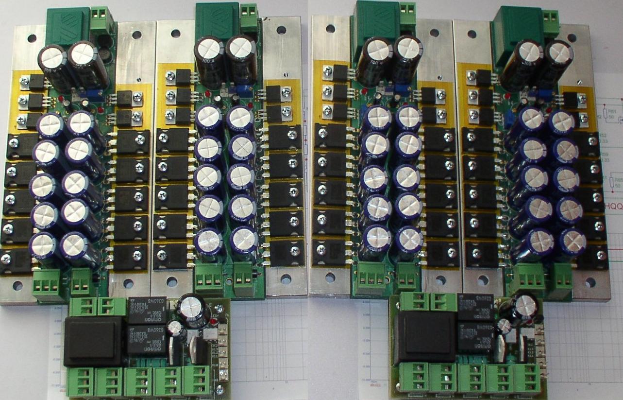
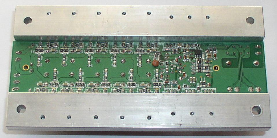
sorry my typo.
What is the voltage gain of the amplifier at each of the test frequencies?
input 300mVpp and output ~10000mVpp measure both voltages using the same instrument. Divide output voltage by input voltage, (lets say you got 10100mVpp & 295mVpp).
The gain is 34.237times = 30.7dB at that test frequency.
Now plot gain vs frequency.
hi!
gud day...
i also did this kind of amplifier on breadboard, but i goto some problems encountered, what should i do if my R15 and R14 get too much heat, i already change it to a 10W 50 ohms??thank you
gud day...
i also did this kind of amplifier on breadboard, but i goto some problems encountered, what should i do if my R15 and R14 get too much heat, i already change it to a 10W 50 ohms??thank you
hi!
gud day...
i also did this kind of amplifier on breadboard, but i goto some problems encountered, what should i do if my R15 and R14 get too much heat, i already change it to a 10W 50 ohms??thank you
Just adjust bias. And stick to your 0,33 ohms!
When I was adjusting my bias I had the same problem.
Anyway, the problem with the bandwith is solved guys. Capacitor C2 is way to high!
At the moment I'm explaining the function of the schematic, the only thing I can't find out is that LED, it's used for thermal stability. But how does it do this?
that LED, it's used for thermal stability.
But how does it do this?
Any diode will decrease voltage across when warmed up.
LED = light emitting diode
The trick here is to place the diodes very close to heatsink. To feel the warmth.
When voltage goes down, then the current through output will be lower.
And the diodes will not decrease voltage.
When heatsink gets cold the voltage across diodes will go up
to give more current.
This stabilize the heat, the current in output stage.
Diodes will counteract the temperature of heatsink.
🙂
If you remember, someone said to glue diode to heatsink.
If in contact the diode will respond better. To stabilize the temperature.
Must be a glue that can take some heat.
I would just bend the diode to be very close to heatsink.
Think should do without glue.
If you remember, someone said to glue diode to heatsink.
If in contact the diode will respond better. To stabilize the temperature.
Must be a glue that can take some heat.
I would just bend the diode to be very close to heatsink.
Think should do without glue.
- Status
- Not open for further replies.
- Home
- Amplifiers
- Solid State
- Mosfet IRFP240/9240
 !
!
