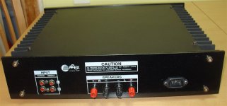
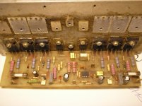
the MOSfet output stage could be biased anywhere from zero mA to full ClassA.
The designer tells us this circuit works with 10mV across 0r47 (~21mA/device).
Why do you think that recommendation is wrong?
Could Borbely's advice for a total bias >=500mA and individual device bias >=100mA also be wrong?
The designer tells us this circuit works with 10mV across 0r47 (~21mA/device).
Why do you think that recommendation is wrong?
Could Borbely's advice for a total bias >=500mA and individual device bias >=100mA also be wrong?
Why do you think that recommendation is wrong?
Could Borbely's advice for a total bias >=500mA and individual device bias >=100mA also be wrong?
Amperage depends on the overall feedback is local feedback must be afraid of a big current.
This bias I suggest to Valenca for the test. You are right, bias can be higer depend of heatsink, new bias adjust circuit is made for that.I think 10mV is to little. About 35mV should be ok with good power supply and cooler.
Regards
VAS transistors biased with 27mA, for outputs 100mA/device with proper heatsink. With high biased VAS no need to use EF with BJTs in output stage.
Regards
Regards
Last edited:
I made version of this amplifier with OP amp in front, VAS biased with 25mA. Good sound, but audiophiles don't like OP amp in front, I can't change what people like or not, no metter what is the best.
This is minimum heatsink (400x100x50mm) if use amplifier for Hi-Fi .
Attachments
Last edited:
Apex, sorry for my absence is that I'm on vacation and it's hard to stop, but I'll still send the pictures as soon as I can!
Thanks!
Thanks!
We wait,Apex, sorry for my absence is that I'm on vacation and it's hard to stop, but I'll still send the pictures as soon as I can!
Thanks!
Regards
If you have pictures of some 'apexaudio' projects please send here:Apex, sorry for my absence is that I'm on vacation and it's hard to stop, but I'll still send the pictures as soon as I can!
Thanks!
Mile Slavkovic | Facebook
Regards
Mosfet replacement
Hi Mile,
Can I substitute 2SK1058 & 2SJ162 for those outputs?
TIA,
>Joel
Philippines
Simple Full Complementary Simetry +/-80V. Voltage amplifier/driver biased with 30mA. This driver circuit stabilized BIAS in output stage. Exelent stability without oscilation, hum and noise, sound great.
RMS Power: 240W 8ohm, 350W 4ohm
Very low efficiency. My amp can in voltage ± 80V, output 700W/4Ω
No this amp is design for IRFPs,Hi Mile,
Can I substitute 2SK1058 & 2SJ162 for those outputs?
TIA,
>Joel
Philippines
Regards
Hv250
I made version of this amplifier with OP amp in front. The MOSFETs used are IRFP9240 (P) and IRFP240 (N). They are assembled in a common source configuration so they can be completely saturated. Good sound, but audiophiles don't like OP amp in front, I can't change what people like or not, no metter what is the best.
I made version of this amplifier with OP amp in front. The MOSFETs used are IRFP9240 (P) and IRFP240 (N). They are assembled in a common source configuration so they can be completely saturated. Good sound, but audiophiles don't like OP amp in front, I can't change what people like or not, no metter what is the best.
Attachments
HV350 is general purpose amp, efficiency is not important, just sound, but with HV250 you have efficiency (maximum power from rail voltage for class AB amp),Very low efficiency. My amp can in voltage ± 80V, output 700W/4Ω
Regards
I made version of this amplifier with OP amp in front. The MOSFETs used are IRFP9240 (P) and IRFP240 (N). They are assembled in a common source configuration so they can be completely saturated. Good sound, but audiophiles don't like OP amp in front, I can't change what people like or not, no metter what is the best.
Hello Mile
Do you mind posting the schematics for the OP based version?
Thanks!
I have two OP based mosfet amplifier, and I will post both schematics,Hello Mile
Do you mind posting the schematics for the OP based version?
Thanks!
Regards
OP based amplifier useing OP in input stage, not for DC servo like thisHello Mile
Do you mind posting the schematics for the OP based version?
Thanks!
http://www.diyaudio.com/forums/solid-state/162081-dc-servo-mosfet-amplifier.html
Regards
Hi, Sorry to start from the beginning. I want to try this HV350 amp🙂. Sorry i don't have experience of MOSFET amplifier design. This is my first project. Are you recommend this amp for first project.?.. If you have interest Please help me to complete my first project.
lot of discussion are going behind the design. so please give me the final circuit and component value.
I finished my PCB design for this amp. I want to start this amp with low power first. I have some questions.
1. I have +33v/0/-33v supply. I want to start from this range. (24v/0/24v transformer)
2. What are the settings should i made before start with this supply range.
3. Is it necessary to connect 4+4 MOSFET for this low power setting.
4. I have 150W/8E woofer. Is it enough for testing.
5. what should be the bios value for this supply range and what are the procedure to set the bios. how to set the bios current.
6. May i use this amp for my subwoofer amplifier.
7. How to calculate the output power of an amplifier.
Thank you. I have lot of interest in this amp🙂. I will post my hardware photograph with in two days. sorry for my English🙁.....
Regards
Udhay
With +/-33V single pair of output FETs is enough, you can see circuit in post #239, and wireing in post #145. Bias adjust to get about 20mV on 0R47/5W resistor. Power will be about 50W on 8R load with +/-33V DC. You can use this amp for any aplication, and I think beginer can build it with my help.Hi, Sorry to start from the beginning. I want to try this HV350 amp🙂. Sorry i don't have experience of MOSFET amplifier design. This is my first project. Are you recommend this amp for first project.?.. If you have interest Please help me to complete my first project.
lot of discussion are going behind the design. so please give me the final circuit and component value.
I finished my PCB design for this amp. I want to start this amp with low power first. I have some questions.
1. I have +33v/0/-33v supply. I want to start from this range. (24v/0/24v transformer)
2. What are the settings should i made before start with this supply range.
3. Is it necessary to connect 4+4 MOSFET for this low power setting.
4. I have 150W/8E woofer. Is it enough for testing.
5. what should be the bios value for this supply range and what are the procedure to set the bios. how to set the bios current.
6. May i use this amp for my subwoofer amplifier.
7. How to calculate the output power of an amplifier.
Thank you. I have lot of interest in this amp🙂. I will post my hardware photograph with in two days. sorry for my English🙁.....
Regards
Udhay
Regards
Last edited:
- Home
- Amplifiers
- Solid State
- MOSFET Amplifier IRFP240/IRFP9240

