In your example, the gain becomes simply less, and the optimum load resistance at which the power will be maximized will have to be determined empirically.
Having built drivers that are capable of over 100Vrms at less than .01% distortion, I don't consider lower gain in the output stage to be a big problem. I consider the poor damping factor of UL and inferior linearity to be a big problem.
I don't design amplifiers to prioritize maximize power delivery to the load. I design them to have low distortion, good damping factor, and "enough" power.
Do not invent your own nonsense. Hafler appears to be mistaken аnd with him the US Bureau too. Or maybe you have patents? For each tube there is an optimal UL% and Hafler wrote about it in patent. The cathode feedback also has % and it necessarily sums with UL% if they work in one output transformer. By the type "modfied-ultralinear" 60% / 40%, which you all the time refer to, but you close your eyes to important % numbers.
For KT88 UL40% is the optimum. Look link. View attachment 621091
For other tubes and modes, there may be anothers %. But this does not mean that the KT88 work at its maximum opportunity at UL20% or at 50% as in the McIntosh diagram. Because the UL's advantage in the patent Hafler as a low distortion like a triode, or even lower, and at the same time high gain as in tetrodes (pentodes).
Or consider the case for EL34 at 60% or even 50% it's all not UL at all but a fake. And such delusional recommendations not of Mullard too!
I am not inventing anything. One example of UL with cathode feedback is for example some old Audio Reasearch amplifier.
Don't know why you keep talking about the KT88. I have only made once an output transformer for a Dynakit amp but never used them for my amps! There are much better pentodes and unfortunately many of these do not like high G2 voltage.
Hafler patents are old. For me there are better ways to build amps as many other people here. Last but not least I still use use and enjoy my beloved zero fb DHT amps (although now someone could enter the discussion and say that a triode is already a device with internal feedback).
Last edited:
All the drain on the contrary! If the driver on the thiod at 100 volts distorts less than 0.01%, then at 50 volts it will distort 0.001%. And this without any tricks! Just less signal and accordingly and less distortion. At the expense of poor damping and lower linearity in the UL, you are poorly formed. Read Norman Crowhurst, Glass Audio 3|96 in his examples on 5881 on a real load UL is better in all respects than a tetrod and even a triode. In the case of applying UL with additional local coupling in the cathodes, 7% + 33% / 60% or 40% / 60% outperforms the damping of the triode with a large separation (R1.4 / R0.32), and most importantly much more in terms of efficiency (22 , 5% against 64%) and on the output of the opportunity, too! Pay attention to the figures, having much more efficiency and UL distortion ability of only 0.85% versus 4.4% distortion on triodes!Having built drivers that are capable of over 100Vrms at less than .01% distortion, I don't consider lower gain in the output stage to be a big problem. I consider the poor damping factor of UL and inferior linearity to be a big problem.
I don't design amplifiers to prioritize maximize power delivery to the load. I design them to have low distortion, good damping factor, and "enough" power.
If you carefully read this book Beam Power Tubes by. O.H.SCHADE from 1938 to which you refer, you should know that distortions decrease in proportion to the depth of feedback. So it is written in this book. However, progress did not stand still either then in the 50s and even now too. David Hafler, 13 years later, showed in his 1951 patent that the non-linearity on the screen grid when local feedback is applied to it changes this ratio and the distortions decrease much more rapidly than the depth of feedback increases. And this is all due to the effect of the combined effect of feedback and partial compensation of nonlinearities between the first and second grids.Here you go:
http://www.clarisonus.com/Archives/TubeTheory/Schade 1938 Beam Power Tubes.pdf
Feedback theory is well described, even for complex systems. Here is the simplest possible case.
Yes, Khafler's patent is old, but he showed the basis of his idea, in which non-linearity on the screen grid when local feedback is applied to it changes the proportion between the depth of feedback and the level of distortion, as a result of which distortions decrease much faster than the depth of feedback increases. And this is all due to the effect of the combined effect of feedback and partial compensation of nonlinearities between the first and second grids. That allows you to keep low distortion by getting a high output power like that of tetrodes. Norman Crowhurst, Glass Audio 3 | 96 showed that even UL can be improved and get even better properties if you understand where to move.I am not inventing anything. One example of UL with cathode feedback is for example some old Audio Reasearch amplifier.
Don't know why you keep talking about the KT88. I have only made once an output transformer for a Dynakit amp but never used them for my amps! There are much better pentodes and unfortunately many of these do not like high G2 voltage.
Hafler patents are old. For me there are better ways to build amps as many other people here. Last but not least I still use use and enjoy my beloved zero fb DHT amps (although now someone could enter the discussion and say that a triode is already a device with internal feedback).
KT88 I took only for the sake of example because it is well studied in the UL and I have on it the corresponding diagrams. For UL, you can take any tetrodes and pentodes, the main thing is to have a screen grid!
KT88 I took only for the sake of example because it is well studied in the UL and I have on it the corresponding diagrams. For UL, you can take any tetrodes and pentodes, the main thing is to have a screen grid!
Unfortunately modern production KT88 is rather poor when compared to the real thing. Those that are decent are too expensive for my taste. One also needs to be careful when buyng potential NOS KT88 because there are a lot of fakes around......I have got other nice pentodes for peanuts and will stick to them. They don't like classic UL, unless I make a tertiary winding which I find totally unecessary.
Read Norman Crowhurst, Glass Audio 3|96 in his examples on 5881 on a real load UL is better in all respects than a tetrod and even a triode. In the case of applying UL with additional local coupling in the cathodes, 7% + 33% / 60% or 40% / 60% outperforms the damping of the triode with a large separation (R1.4 / R0.32), and most importantly much more in terms of efficiency (22 , 5% against 64%) and on the output of the opportunity, too! Pay attention to the figures, having much more efficiency and UL distortion ability of only 0.85% versus 4.4% distortion on triodes!
According to Crowhurst partial cathode followers like the "modified ultralinear" is just as good. True cathode followers are also just as good but not practical.
Don't forget to check non-linear distortion caused by the interaction of the amplifier with speakers. That's what matters. Forget the non-sense of "high damping factor is better" and tiny THD numbers measured on dummy loads. As for the triodes, unfortunately Crowhurst used very poor triodes for his THD comparisons (i.e. triode strapped 6L6). This only means don't use pentodes as triodes in general. There are exceptions of course....
Last edited:
In this case, you can say with the same success - forget about the fictitious measurement and learn to hear with your ears, because the main thing is the ears, and not devices. UL sounds beautiful on the real load and at the same time is much louder than triodes for those who have a hearing to hear at least a difference in volume.Don't forget to check non-linear distortion caused by the interaction of the amplifier with speakers. That's what matters. Forget the non-sense of "high damping factor is better" and tiny THD numbers measured on dummy loads. As for the triodes, unfortunately Crowhurst used very poor triodes for his THD comparisons (i.e. triode strapped 6L6). This only means don't use pentodes as triodes in general. There are exceptions of course....
This is not a problem at all if there is a fantasy. I have already quoted five times James Moir that there are circuits that can almost the same thing as UL and there are not overloaded screen grids with excessive voltage.Unfortunately modern production KT88 is rather poor when compared to the real thing. Those that are decent are too expensive for my taste. One also needs to be careful when buyng potential NOS KT88 because there are a lot of fakes around......I have got other nice pentodes for peanuts and will stick to them. They don't like classic UL, unless I make a tertiary winding which I find totally unecessary.
http://www.wowhififever.com/LV_60/Neuman%20LV60.htm
Last edited:
If you carefully read this book Beam Power Tubes by. O.H.SCHADE from 1938 to which you refer, you should know that distortions decrease in proportion to the depth of feedback. So it is written in this book. However, progress did not stand still either then in the 50s and even now too. David Hafler, 13 years later, showed in his 1951 patent that the non-linearity on the screen grid when local feedback is applied to it changes this ratio and the distortions decrease much more rapidly than the depth of feedback increases. And this is all due to the effect of the combined effect of feedback and partial compensation of nonlinearities between the first and second grids.
Do you mean that progress after 50'Th did stand still? Not at all!
Back in 1970'Th when I graduated TIASUR our professors were even progressivier than David Hafler in 1951! They taught us how to solve differential equations optimizing sophisticated feedback loops! And even then progress did not stop. Did you read Morgan Jones' books? Highly recommend! Can you imagine using Morgan Jones's name in battles on forums? Wow! Go for it! 🙂
Somewhere, in some thread here, someone did a uTracer curve plot of a pentode for varying %UL. It was an eye opener. With higher %UL, the pentode knees drop lower and lower, with the plate curves curving up progressively more like triode curves. It is a smooth continuous transformation, with no sign of some "optimum" %UL. Really just showing the continuous variation of effective Mu between the screen grid triode case and the pentode case (being a very high Mu triode with a truncated/left-shifted origin, due to screen current absorption).
All % UL cases are actually using non-linear triode N Fdbk (even up to the pentode case theoretically). However, pentodes typically are operated with a low Z primary OT for max power at low B+, and do not make effective use of their high Rp plate N Fdbk.
I think the "optimum" %UL found historically may just be for a specific primary Z and specific tube. If one goes to higher %UL using those curves, then the optimum primary Z would increase and higher B+ would be needed to get the same power (as usual for triodes). Specific tubes of course have max B+ limits, so this can not be carried out indefinitely in practice.
----
The LV amplifier linked appears to use plate to driver cathode "local" N Fdbk.
This puts a lot more gain in the "local" loop, so will certainly reduce distortion effectively. And it allows the output tube(s) to keep functioning at max capability (grid 2 voltage held constant). Stability with all that loop gain may be an issue.
----
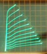
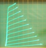
The most unique non-linear compensation by far occurs in Crazy or Twin drive for pentodes. And it is not even N Fdbk, but feed forward instead. It works well beyond all reasonable expectation. Example below: (1st pic normal grid1 drive, 2nd pic Twin/Crazy drive, same 26DQ5 for both pics)
All % UL cases are actually using non-linear triode N Fdbk (even up to the pentode case theoretically). However, pentodes typically are operated with a low Z primary OT for max power at low B+, and do not make effective use of their high Rp plate N Fdbk.
I think the "optimum" %UL found historically may just be for a specific primary Z and specific tube. If one goes to higher %UL using those curves, then the optimum primary Z would increase and higher B+ would be needed to get the same power (as usual for triodes). Specific tubes of course have max B+ limits, so this can not be carried out indefinitely in practice.
----
The LV amplifier linked appears to use plate to driver cathode "local" N Fdbk.
This puts a lot more gain in the "local" loop, so will certainly reduce distortion effectively. And it allows the output tube(s) to keep functioning at max capability (grid 2 voltage held constant). Stability with all that loop gain may be an issue.
----
The most unique non-linear compensation by far occurs in Crazy or Twin drive for pentodes. And it is not even N Fdbk, but feed forward instead. It works well beyond all reasonable expectation. Example below: (1st pic normal grid1 drive, 2nd pic Twin/Crazy drive, same 26DQ5 for both pics)
Attachments
Last edited:
The most unique non-linear compensation by far occurs in Crazy or Twin drive for pentodes. And it is not even N Fdbk, but feed forward instead. It works well beyond all reasonable expectation. Example below: (1st pic normal grid1 drive, 2nd pic Twin/Crazy drive, same 26DQ5 for both pics)
So, I was wrong when stated that the best UL ratio is zero. It appeared from your tests, there is an optimum, and it is in even negative UL ratio. ;-)
I suppose one -could- look at it that way!
Except there is a resistor with I to V conversion for grid1 involved as well. Maybe one could even make a case for the grid1 current causing a voltage feedback at grid1 (rather than a feed-forward scenario). Looks more like negative Fdbk then however. Well, Crazy it is.
Anatoly, your suggestion would seem to call for an experiment. Use the positive going UL tap with a resistor to grid 1. Grid2 still being driven. (assumes the output is linear with the input, to generate the same conditions as Crazy/Twin drive would.)
Last edited:
At the expense of poor damping and lower linearity in the UL, you are poorly formed. Read Norman Crowhurst, Glass Audio 3|96 in his examples on 5881 on a real load UL is better in all respects than a tetrod and even a triode. In the case of applying UL with additional local coupling in the cathodes, 7% + 33% / 60% or 40% / 60% outperforms the damping of the triode with a large separation (R1.4 / R0.32), and most importantly much more in terms of efficiency (22 , 5% against 64%) and on the output of the opportunity, too! Pay attention to the figures, having much more efficiency and UL distortion ability of only 0.85% versus 4.4% distortion on triodes!
I don't know why you keep talking about triodes when you respond to me. I am talking about pentodes, run with constant screen-cathode voltages and with plate-to-grid feedback (whether parallel applied or series applied makes no difference). I am not talking about triodes. Triode-connected pentodes have higher plate resistance and poorer linearity than pentodes with local feedback applied to control grid and set for the same circuit "mu". (That is a big hint right there that feedback should be applied to the electrode that caused the error in the first place!)
What you say above is simply not true. I just built a pentode amp with 30% voltage feedback that has an open-loop Zout on the transformer secondary of 2.4 Ohms (including output transformer losses!). No open-loop UL amp can come close to that. The effective plate resistance of the circuit is simply too high. This is plainly obvious by looking at the UL curves and drawing feedback curves as outlined in the Otto Schade's paper.
The effective plate resistance of a pentode with 30% voltage feedback is far lower than the same pentode connected as triode (or UL of *any* ratio). Of course gain is lower but that is not what I consider a big problem since I am capable of designing a good low-distortion high-swing driver and I am interested in driving my transformers with low-impedance power tube circuits with excellent linearity.
re: post 31 experiment:
That would make it load sensitive however. More loading would mean less grid1 drive. So that will have a higher output Z than the Crazy/Twin case.
What is needed is something to lower the output Z for Crazy/Twin drive. (Well, conventional "Schade" output plate to driver plate N Fdbk would still do that.)
Last edited:
What is needed is something to lower the output Z for Crazy/Twin drive.
Some series or parallel applied voltage feedback whether local or global to the amplifier should do the trick. 🙂
I suppose one -could- look at it that way!
Except there is a resistor with I to V conversion for grid1 involved as well. Maybe one could even make a case for the grid1 current causing a voltage feedback at grid1 (rather than a feed-forward scenario). Looks more like negative Fdbk then however. Well, Crazy it is.
Anatoly, your suggestion would seem to call for an experiment. Use the positive going UL tap with a resistor to grid 1. Grid2 still being driven. (assumes the output is linear with the input, to generate the same conditions as Crazy/Twin drive would.)
What's the point in driving G1 from secondary, when anyway power needed to drive G2 is higher? And are you sure that V/I conversion is needed? Did you try to drive both grids from different followers, with different signal levels?
Yes, driving grid2 from the positive Fdbk UL tap would make better sense. (since output is assumed linear with input for Crazy/Twin drive) Then only low level signal would be needed for grid 1. Driving grid1 thru a resistor would seem somewhat flimsy for control though, probably extremely high Z output that way. It might even latch up, with grid1 unable to turn it off! Maybe no choice but to use V drive for grid1 that way. I suppose one could try putting the resistor over in the grid2 to (opposite) UL link.
The idea of driving grid1 and grid2 with different scaled V drives (something like the g2/g1 mu ratio) has been discussed before. And George (Tubelab) has done some experiments, maybe others too. No doubt works, but how linear?
I think the resistor network for grid 1 (in the positive region in Crazy/Twin ) is necessary though for the near miraculous linearization seen in Crazy/Twin drive. (likely related to the SQRT function involved in grid current interception and the 3/2 and 2.0 power laws for grid 2 versus grid 1. )
.
to Spread
"triode-connected pentodes have higher plate resistance and poorer linearity than pentodes with local feedback applied to control grid and set for the same circuit "mu"
These are some tests "on the road" of pentode in triode connection
Vdc=320 v, Ia=50 mA
Vin 1 volt and 5 volt directly from AP1 to circuit; load L= 28 H with a Z o f more than 400 Kohm at 2 Khz ( test frequency)
I think will be difficult to get a lower Rp with other then triode connection, about the linearty I check them with Sofia and seems to have all a good shape.
Walter
Attachments
Last edited:
New push-pull tube amplifiers. Menno van der veen
http://www.next-tube.com/articles/Veen2/Veen2EN.pdf
Next-Tube. Ñòàòüè ïî òåìàòèêå àóäèîàïïàðàòóðû.
MODERN HIGH END VALVE AMPLIFIERS BY MENNO VAN DER VEEN
http://docslide.net/documents/modern-high-end-valve-amplifiers-by-menno-van-der-veen.html
http://www.next-tube.com/articles/Veen2/Veen2EN.pdf
Next-Tube. Ñòàòüè ïî òåìàòèêå àóäèîàïïàðàòóðû.
MODERN HIGH END VALVE AMPLIFIERS BY MENNO VAN DER VEEN
http://docslide.net/documents/modern-high-end-valve-amplifiers-by-menno-van-der-veen.html
Last edited:
I think will be difficult to get a lower Rp with other then triode connection,
It depends solely on feedback loops. For -1 gain you can get Zo = 1/gm -- of course it is much lower than in triode connection, it is obvious.
Thanks to the nested loop I can get higher gain through loops on higher frequency that with a global loop only, and as the result, lower than triode output resistance, lover distortions, with higher than in triode power.
GUNFU, I think you will draw different conclusions about Crowhurst if you examine his claims from a marketing perspective. In particular the U-L tap location should vary depending on design goals, and needs to consider what the tube characteristics are *AT THE PARTICULAR OP CHOSEN*, not to mention the detail of that OP.
cheers,
Douglas
cheers,
Douglas
- Home
- Amplifiers
- Tubes / Valves
- More on Output Stage Local Feedback