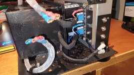
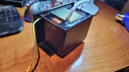
Tonight I removed the moulds from the transformers.
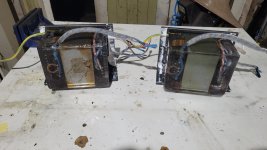
I took a bit of work to get the buggers off and I have a bit of cleanup to do to remove the silicon, runs etc.
I reckon the look pretty cool despite the mess.
I might want to apply a bit of epoxy to the gap between the bottom of the transformer and the bracket so that it doesnt rust in the future. A decent chunk of paint came off during the process.
Nothing short of amazing SF! Your attention to detail is so impressive. Can't wait to see your final pics.
Thanks for the compliments guys.
Clear coating of the mahogany is occurring. 2 coats so far. I will probably go all the way and lay on 5 coats.
I've mostly finished painting. Only the outside of the side panels to go.
I spent a good bit of time last night removing the schmoo from the bracket and wires.
Things look pretty good so far. Tonight I tested continuity across all the secondaries. Everything checks out.
I did nick a wire here:
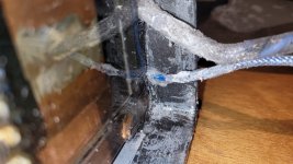
Not all the way through the insulation. This is 1000v rated wire running 12v so I'm not worried about a wee nick.
More annoying was this one:
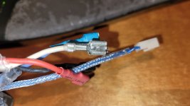
I'm not entirely sure how epoxy manage to get there. Perhaps it rolled around in some runoff on the bench or somehow dribbled down to the spade and under the heatshrink but not on the rest of the wire?
Annoying either way. I will make a half heated attempt at removing it but I will probably just replace the terminal.
Here's some picks after a 'tidy'
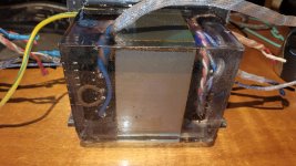
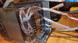
I did quite a bit of damage to the paint during the schmoo removal process so I will need to do some more painting.
I am also thinking I will chuck another layer of braid or heatshrink (not sure which yet) over the wires to hide the schmoo I can't remove.
I am also thinking about what to do about this:
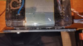
This gap from the mould between half of the 'pot' and the bracket. There is exposed metal under there now from the mould removal as well as a bit of cracking.
I am thinking of siliconing some 'cheeks' onto the side of the 'pot' and filling up the gap with epoxy to protect the metal and fix the cracks.
Then I will worry about repainting the bracket.
I am torn between leaving the epoxy clear for the coolness of seeing the transformers inside.
Or painting it all in hammered black to match the rest of the chassis.
Clear coating of the mahogany is occurring. 2 coats so far. I will probably go all the way and lay on 5 coats.
I've mostly finished painting. Only the outside of the side panels to go.
I spent a good bit of time last night removing the schmoo from the bracket and wires.
Things look pretty good so far. Tonight I tested continuity across all the secondaries. Everything checks out.
I did nick a wire here:

Not all the way through the insulation. This is 1000v rated wire running 12v so I'm not worried about a wee nick.
More annoying was this one:

I'm not entirely sure how epoxy manage to get there. Perhaps it rolled around in some runoff on the bench or somehow dribbled down to the spade and under the heatshrink but not on the rest of the wire?
Annoying either way. I will make a half heated attempt at removing it but I will probably just replace the terminal.
Here's some picks after a 'tidy'


I did quite a bit of damage to the paint during the schmoo removal process so I will need to do some more painting.
I am also thinking I will chuck another layer of braid or heatshrink (not sure which yet) over the wires to hide the schmoo I can't remove.
I am also thinking about what to do about this:

This gap from the mould between half of the 'pot' and the bracket. There is exposed metal under there now from the mould removal as well as a bit of cracking.
I am thinking of siliconing some 'cheeks' onto the side of the 'pot' and filling up the gap with epoxy to protect the metal and fix the cracks.
Then I will worry about repainting the bracket.
I am torn between leaving the epoxy clear for the coolness of seeing the transformers inside.
Or painting it all in hammered black to match the rest of the chassis.
Super cool look SF!
If you keep them clear, a neat visual effect would be to install an LED in the epoxy for ‘glowing’ trafo’s.
If you keep them clear, a neat visual effect would be to install an LED in the epoxy for ‘glowing’ trafo’s.
I thought of putting some LEDs in there after it was all epoxied up.
There was some convenient taps too....
It will all be safely encased in the chassis and not visible anyway but maybe next time.
I have a good stash of these salvaged transformers for future projects so watch this space.
There was some convenient taps too....
It will all be safely encased in the chassis and not visible anyway but maybe next time.
I have a good stash of these salvaged transformers for future projects so watch this space.
I've been beavering away.
The mahogany is looking gorgeous with its clear coat
The chassis is finished with paint.
I think I have figured out what to do with the power transformers.
I will polish up the 'front' and top of the transformer so they can be seen into during servicing.
The sides are a bit too scabby and beaten up for keeping clear so I think I will paint the sides when I repaint the bracket.
Before doing that I need to run a quick test fit of the potted up transformers and make sure they still fit properly in the chassis.
I may have gone a little oversize in one direction and this could cause problems.
More on this soon.
The mahogany is looking gorgeous with its clear coat
The chassis is finished with paint.
I think I have figured out what to do with the power transformers.
I will polish up the 'front' and top of the transformer so they can be seen into during servicing.
The sides are a bit too scabby and beaten up for keeping clear so I think I will paint the sides when I repaint the bracket.
Before doing that I need to run a quick test fit of the potted up transformers and make sure they still fit properly in the chassis.
I may have gone a little oversize in one direction and this could cause problems.
Test fits are very useful.....
So it turns out I did make my mould a bit large in one direction which meant the transformer was going to foul the side of the chassis.
My maths was obviously a bit quick and dirty and with not enough thinking....
So a quick zhush with the die grinder to oval out the holes by 5mm allowed me to slide the transformers back towards the centre enough to fit the transformers in. The other option was remove about 5mm of epoxy which didn't seem like a good idea.
With that part sorted I could finalise the transformers. I decided that they were a bit scabby to keep the epoxy clear without waaaaaaay too much work.
So I've decided that I will paint the transformer/bracket assembly on all sides except the top.
The tops ended up all purdy and clear and didn't require any work unlike the sides.
So paint to hide my messy casting work with a 'window' on top too see the coolness inside.
I will definitely pot transformers differently in future. And since I have 2kg of epoxy left over I will definitely be potting more....
Well everything was going well.....
Assembly finished.
Dim bulb test went fine.
And then the problems started.
The right channel showed nothing on the scope at the output. Hopefully just a wiring error. It was just before bed time so no serious investigation.
The left channel has 30vdc at the speaker jacks and a 1ish vac signal at the output at idle. Once again no serious investigation due to bed time. I'm not sure if it is +ve or -ve dc but suffice to say I don't think this is a wiring issue.
I am afraid I have damaged some of the to92 semis pushing and pulling the little heatsinks on and off.
The best laid plans of mice and men....
Careful voltage measurements should show what has happened. Check the rails first including the supply to the opamp.
I will get onto the right channel later tonight and fix the hopefully simple wiring issue.
Exercise and wife time first of course.
Then comes the left channel.... I'll print out the schematic and poke around.
Exercise and wife time first of course.
Then comes the left channel.... I'll print out the schematic and poke around.
Well,
The right channel works fine. I can only assume a connection was loose between my sig gen and the input last night.
Now onto the left channel.
The right channel works fine. I can only assume a connection was loose between my sig gen and the input last night.
Now onto the left channel.
-36Vdc at the output on the left channel.
-48vdc at pin4 on the opamp.
Full continuity between the -ve rail and the ground.
I suspect I have found the problem. Now I just need to find where on earth the short is.
-48vdc at pin4 on the opamp.
Full continuity between the -ve rail and the ground.
I suspect I have found the problem. Now I just need to find where on earth the short is.
False Alarm.
Just the usual level of continuity one gets across a large linear power supply.
I think the fault is on the amp board somewhere. I am rigging up some extension leads to the transformer wiring so that I can run the psu+amp+heatsink assembly outside of the chassis for easy measurement.
More on this tomorrow.
Is the ground connected? Measure the voltage on pin 7 of the opamp. If that is -48v as well then the ground is missing.
Having pulled the psu/amp module out and tested things again with some extensions leads.
Things seem normal again. I can only assume there was a loose ground connection from the psu to the amp board.
I get a nice clean sine wave at the output.
I will now button everything back together and test some more.
It might be I can post some glamour shots of the final build in a few days. We'll see how I go.
That does sound like the most likely reason but its always good to know for sure if possible rather than wondering if some intermittent issue is lurking. Check check and double check everything as you put it all together.
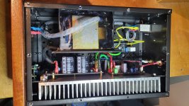
All buttoned up minus the top plate and its passed testing.
I even took it to clipping into 4R too see what my power consumption is like.
35W at Idle. 160W at clipping into 4R.
Time put on the top plate and button tighten up all the screws. Hopefully never to be undone again.
I even took it to clipping into 4R too see what my power consumption is like.
35W at Idle. 160W at clipping into 4R.
Time put on the top plate and button tighten up all the screws. Hopefully never to be undone again.
G'day Guys,
The build is finally done. It's only taken me 7 months.
Probably something like 300 hours with something like 10 hours per week.
The results are worth the effort. They look awesome and sound even better than they look.
Here's the mahogany in the morning sunlight:
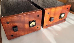
And now the glamour shots on my daughters play table with a white sheet over it:
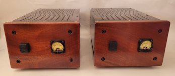
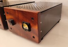
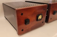
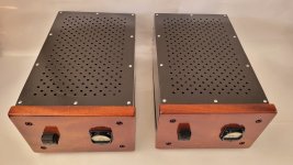
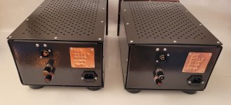
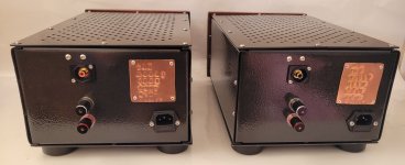
The build is finally done. It's only taken me 7 months.
Probably something like 300 hours with something like 10 hours per week.
The results are worth the effort. They look awesome and sound even better than they look.

Here's the mahogany in the morning sunlight:

And now the glamour shots on my daughters play table with a white sheet over it:


- Home
- Amplifiers
- Solid State
- Mooly's MMAMFM Monoblocks - A build log

