Hi Ipanema
For a decision of the size of Rb (120 ohms), I used the following formula:
Rb x (Is – Ib) = Vbe + Re x (Ib x hFE)
where
Rb x (Is – Ib) = Voltage across Rb
Is = supply dc current (LM6181)
Ib = base dc current
Ib x hFE = Ic
Vbe = transistor turn-on voltage
And, I tried to satisfy the following three conditions:
1. All four transistors to be turned on
2. Ic (dc bias current) to be as small as possible
3. What should be proper size of Rb for the conditions 1 and 2?
If hFE is too high, could be difficult to meet the conditions 1 and 2.
No, I have not tried it with Darlington yet.
Regards
Hi Ipanema
If your TR has hFE=1000, just keep the 120 ohms and add one 1k resistor (or similar size) at the base of the TR. This would solve the problem. In this case, I believe that your TR should have big enough Ic current rating.
Regards
If your TR has hFE=1000, just keep the 120 ohms and add one 1k resistor (or similar size) at the base of the TR. This would solve the problem. In this case, I believe that your TR should have big enough Ic current rating.
Regards
Hi Jh6you,
Interesting. Do you mean parallelling 120R with 1k?
Thanks and you are really helpfull.
Regads,
Ipanema
Interesting. Do you mean parallelling 120R with 1k?
Thanks and you are really helpfull.
Regads,
Ipanema
Nelson Pass said:There seems to be significant interest in possible ways of getting SuperSymmetric operation on a monolithic chip (see the Gainclone X thread in the Solid State forum), and there have been a lot of imaginative solutions put forward, which is really great, although I don't see any of them actually working as an X circuit.
(BTW, SuperSymmetry is a trademark of Pass Laboratories)
I think perhaps it's time to pull something out of the bag and start a new thread, catering to this interest but with a little bit different direction.
Herewith I would like to present a method of doing this with a pair of op amps (or a dual op amp if you like) of the "current feedback" variety. As you may know, current feedback op amps look like regular op amps except that the (-) input pin is low impedance. They are distinguished by exceptionally wide bandwidth and stable operation, mostly because the feedback network also functions as gain degeneration for the input stage.
Below you (hopefully) see a diagram showing two such op amps interconnected. Each consists of a complementary pair of input followers (actually just buffers, and not conceptually significant) forming the (+) input which drive the actual complementary input devices, where the Emitters form the (-) input to the op amp. These devices in turn drive a pair of complementary output devices whose collectors form the output.
Each of these op amps is a slightly simplified version of commercially available parts. Just go to National Semiconductor's web site and look for "current feedback" op amps.
What will be unusual here is that we have joined the (-) inputs of the two op amps to form the SuperSymmetric connection between them. Each of the non-inverting (+) inputs operates at virtual ground by virtue of the feedback from the output of the opposite amplifier. This effectively makes the (+) inputs of the op amps behave as if they were (-) and vice versa.
R1 = R3, R2 = R4, and the gain is set by R2/R1. The input impedance is R1 if driven from a single-ended source, or 2*R1 from a balanced source. Any undriven inputs should be grounded.
R0 sets the open loop gain of the system, and can be adjusted upward for greater stability, or downward for more feedback. This is a good place for a potentiometer for those who like to explore these issues.
The output, of course, is balanced, and best performance is obtained by using it balanced. The input can be operated balanced or not, but gives slightly better performance when driven by a balanced source.
I haven't yet run across an example of a monolithic higher power op amp using current feedback on the market, but there is no reason that one would not exist. If you find one, it will probably make a dandy SuperSymmetric power amplifier, but until then we have to content ourselves with low power.
Or build something discretely......
Happy Valentine's Day.
Hi Nelson
I've just noticed this thread and I find your topology interesting.
However I am kind of puzzled about the term 'current feedback'.
It looks to me like a compound diamond differential input rather than current feedback, feedback is for me shunt resistors...
Am I right?
I found something 'philosophycally' very close to your design - was this an inspiration?
Attachments
Additional question.
Dakfenriz's circuit looks like an inverting votage feed back which is proposional to the input current. As far as I understand, to be a current feedback amplifier, the feedback voltage (or current) is to be sampled from the "output current." Right?
Regards
jH
Dakfenriz's circuit looks like an inverting votage feed back which is proposional to the input current. As far as I understand, to be a current feedback amplifier, the feedback voltage (or current) is to be sampled from the "output current." Right?
Regards
jH
Re: Re: Monolithic SuperSymmetry with Current Feedback
There is confusion about what "current feedback" means.
When op amps came out with a low impedance negative input,
the marketing departments labeled them current feedback,
but they were not taking feedback from the output current. An
unfortunate label that we have ended up with.
Is that a Sansui circuit?
darkfenriz said:I've just noticed this thread and I find your topology interesting. However I am kind of puzzled about the term 'current feedback'. It looks to me like a compound diamond differential input rather than current feedback, feedback is for me shunt resistors...Am I right?
I found something 'philosophycally' very close to your design - was this an inspiration?
There is confusion about what "current feedback" means.
When op amps came out with a low impedance negative input,
the marketing departments labeled them current feedback,
but they were not taking feedback from the output current. An
unfortunate label that we have ended up with.
Is that a Sansui circuit?
Yes, according to Steven it is Sansui from 1982.
Both sansui and your circuit on te beginning of the thread have much in common I think. By putting a single resistor between low-Z inputs you created what sansui calls 'diamond'. Something like 'redefinition' of the same circuit..? It seems that different reasoning and different ways of thinking do sometimes lead to the same circuits. Of course I don't deny some novelty, you use different input stage and no output followers but the essence of both circuits seems very similar. Am I right?
regards
I think you could throw out the diamond differential, and the
circuits would still be similar, as they both take balanced
feedback. At the same time, having the diamond differentials
gives another similarity to the monolithic "current feedback"
circuit, so there's apprently no end to the fun.
😎
circuits would still be similar, as they both take balanced
feedback. At the same time, having the diamond differentials
gives another similarity to the monolithic "current feedback"
circuit, so there's apprently no end to the fun.
😎
CFA Circlo Symmetry
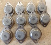
Sorry for necroing. I've got, by an accident, approximately 100 pcs of old SITs.
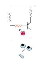
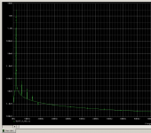
Attached is a PSpice conceptual scetch of CF monolithic circlo kinda symmetry based on original idea.
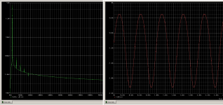
Simulated with values shown.
It seems though that the bias resistors are in series with the gate feed which creates distortions, especially at higher frequencies. However most circlo circuits usually have around 100 Ohms in bias/return.
Sincerely,
Alex
Sorry for necroing. I've got, by an accident, approximately 100 pcs of old SITs.
Attached is a PSpice conceptual scetch of CF monolithic circlo kinda symmetry based on original idea.
Simulated with values shown.
It seems though that the bias resistors are in series with the gate feed which creates distortions, especially at higher frequencies. However most circlo circuits usually have around 100 Ohms in bias/return.
Sincerely,
Alex
Attachments
....I've got, by an accident, approximately 100 pcs of old SITs....
Hundred of old SIT's 😀😀 what is reference and semiconductor company brand ?
Congratulations 🙂
It's КП801А and КП802А. USSR made circa 1991. The former one specifically designed for audio, the latter for SMPS. DS are in Russian, for sure. Info is kinda scarce.
However the point was to have current feedback topology utilized in supersymmetry mode with X-coupled feedback. Any suggestions appreciated. P.S. Models used are of 2SK82 made by Michael Rothacher.
However the point was to have current feedback topology utilized in supersymmetry mode with X-coupled feedback. Any suggestions appreciated. P.S. Models used are of 2SK82 made by Michael Rothacher.
Attachments
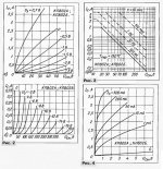

Almost forgot: 801
Rds=2.2 (@Vgs=0)
S=0.600mhOs
Vgs(off)= -30V
Udg max=110V
Pmax ave 60W
Pmax abs 200W
Ic means Id(rain)
Uси means Uds
Uзи means Ugs
B goes for Volt
Cheers,
Alex
Rds=2.2 (@Vgs=0)
S=0.600mhOs
Vgs(off)= -30V
Udg max=110V
Pmax ave 60W
Pmax abs 200W
Ic means Id(rain)
Uси means Uds
Uзи means Ugs
B goes for Volt
Cheers,
Alex


Russian SIT's that interesting
Less than $6.5 each at sources in the Ukraine
Design and production initially was @ NEVZ with the sign on device resembling @ symbol. Leftovers are still on avail from time to time.
Designer since turned on "maverick mode" and everywhere he emerged at the SIT production has started. Yet another two plants still exist. See attach for one. Specs do indeed differ from the original ones.
@Zen Mod No way it would be reasonable to assist in the procurement process.
NEVZ КП926 (ПК15) is somewhat equivalent to 802 and is high voltage device. And yes there are designs as well as real audio gear utilizing 926 instead of tubes. Still in production(?). One may ask guys form Novosibirsk itself. http://www.ru.nevz.ru/downloads/fpdf/PP/tranzistor.pdf
NOS devices should have really even and matte tinned surface. 926 and ПK15 do not have coating (or used to) and rather look like made of cheap stainless steel.
Attachments
Last edited:
- Status
- Not open for further replies.
- Home
- Amplifiers
- Pass Labs
- Monolithic SuperSymmetry with Current Feedback