jh6you said:Mmmm...
Now it seems to work as Jan Didden said.
I see the output node voltages close to zero.
And the node voltages at inverting input terminals are also virtually zero.
I will see others tonight.
JH
Nice, I'll try that too, with my components.
Did you connect a load? And looked with the scope?
How much output do you have?
Could we build a 300W for Dj?

Hey, 
are you shure with the feedback on the same side
I am not
Progress 80%
Any reason why the Ops have to be in inverted mode 😕
are you shure with the feedback on the same side
I am not
Progress 80%
Any reason why the Ops have to be in inverted mode 😕
Oh yeah, maybe the feedback needs to come from the other side, and you need to go into the +inputs, not the -inputs.
Nelson,
are you kidding with us
As I already mentioned before, I am a total newbie to amp building.
But what I think, is that if the OPs output goes positive, the same side Transistors output goes negative. The other side transistors output goes positive, so it has to be fed back to the Ops inverting input.
Error ?
I tested my 95% progress-setup with noninverting Ops and feedback from the other side and it seems to work. Nothing blows.
Unfortunately my regulated 15V supply likes to shut down near 1A.
So, the noninverting inputs of the OPs are still totally open, no resistors to nowhere...
With PSU shut down = +/- 5V the wet finger test gives a crying sound from the speaker, and when another finger is to ground, then I have 100Hz 😎
Strange is that without speaker I have 8V DC to ground from each output = 16 V total, but when I connect the speaker, it doesnt blow, even if the PSU doesnt shut down, the DC goes to 0 and I hear only very very silent 100Hz hum.
My problem is, I have no symetric source, I will try a transformer. Or one input to ground.

No RC on the output but doesnt seem to be oscillating.
And the 4 input resistors still missing.
I chosed 2x0,5A bias only because my PSU can only deliver 1A !!!!!
are you kidding with us
As I already mentioned before, I am a total newbie to amp building.
But what I think, is that if the OPs output goes positive, the same side Transistors output goes negative. The other side transistors output goes positive, so it has to be fed back to the Ops inverting input.
Error ?
I tested my 95% progress-setup with noninverting Ops and feedback from the other side and it seems to work. Nothing blows.
Unfortunately my regulated 15V supply likes to shut down near 1A.
So, the noninverting inputs of the OPs are still totally open, no resistors to nowhere...
With PSU shut down = +/- 5V the wet finger test gives a crying sound from the speaker, and when another finger is to ground, then I have 100Hz 😎
Strange is that without speaker I have 8V DC to ground from each output = 16 V total, but when I connect the speaker, it doesnt blow, even if the PSU doesnt shut down, the DC goes to 0 and I hear only very very silent 100Hz hum.
My problem is, I have no symetric source, I will try a transformer. Or one input to ground.
No RC on the output but doesnt seem to be oscillating.
And the 4 input resistors still missing.
I chosed 2x0,5A bias only because my PSU can only deliver 1A !!!!!
This one works perfect:

Loud and clear, no audible distortion, no turn-on-plopp, no DC offset, no caps, no feedback from outputstages.
I just reduced bias because of my weak PSU.
Loud and clear, no audible distortion, no turn-on-plopp, no DC offset, no caps, no feedback from outputstages.
I just reduced bias because of my weak PSU.
MSSCF
Bernhard,
Are you sure? There is nothing to control the output voltage, it would be pure luck (in this schematic) if the outputs had no offset. And I don't easily accept pure luck.
But I think the original (post 157) schematic has a basic problem, in that if say the left hand opamp tries to null its output, the resulting opamp output current which goes into the right hand opamp will upset THAT balance, and vice versa. The cross-coupling must be otherwise. I think that is also what Nelson was pointing to above.
Just have no time now, will come back later.
Jan Didden
Are you sure?
Yes, I am shure.
No, there is 0,25V on one side and 2,2V on the other side.
The 2,2V still increase with warming up 😎
But these Voltages behave like if they come from a very high impedance source. You could connect even the most sensitive tweeter without a cap...
I have fixed nonmagnetic 10% resitors for the 135ohms, that gives the offset, I found, by adjusting these, I get 0Volts very easy.
There was may be a mistake in one of my earlier posts, when I said that if the OP output of one side goes positive, the output of the same side transistor output goes negative.
I have to think, spent the whole night with this amp and new CD of cradle of filth

I suspect a few things, why connecting the feedback to the output gives problems in my design.
MSSCF
Just looked at it again, there is a problem with the circuit as it stands. R19 should really be split into two, say 2 x 10 or 20 ohms, with the mid connection grounded. That makes the two halves independent, each should be OK to null the output offset. Then drive it differentially for a differential output.
If you drive only one side, the other half just provides a virtual ground to the load and could be deleted.
This really is a bridge circuit, with two independent halves. The original connection through R19 just makes them chase each other ad infinitum.
Look at it this way. The opamp outputs really are an extra input as far as each half is concerned. This input you have no control over, and it is fed with the ERROR signal of the other half which results when it tries to null its output. You have to decouple the two and that can be done by splitting R19 and grounding the midpoint.
Jan Didden
R19 should really be split into two, say 2 x 10 or 20 ohms, with the mid connection grounded.
Do you mean R9
Ok, anyway my circuit works, as far as the feedback comes from the OP output, also if I use the OPs in inverting mode, no difference.
Now I added 4 pots to adjust offset, works fine.
Just when I connect the feedback to the Transistor output, I have 15V DC offset.

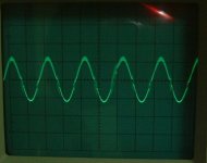
This post shows sine waves at 1kHz.
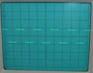
The next post square waves also at 1kHz.
It seems there is certain crossover distortion. I have not tried the speakers yet as I wonder whether the waves look okay. Would you please review the waves? Thanks.
JH
The next post square waves also at 1kHz.
It seems there is certain crossover distortion. I have not tried the speakers yet as I wonder whether the waves look okay. Would you please review the waves? Thanks.
JH
Attachments
MSSCF
Yes, there is xover distortion, also oscillatory bursts on the pos side (also shown by the sq wave overshoot on the rising edge).
When not driven, what is the DC ACROSS the output emitter resistors? (I think Q9, 10, 11, 12).
Was your scope DC coupled? What was the load resistor? Both sides driven? DC across load resistor and from both sides of load resistor to gnd if not driven?
I was referring to the 220 ohms resistor between the two opamp outputs, don't have the schematic here, thought (from the top of my head) that it was R19. Could be wrong.
Jan Didden
JH,
I saw you have only 100mV across these resistors.
Is that still classA ? Iam afraid your amp runs in classC 🙁 with heavy distortion.
I have reduced bias also, due to my PSU problem, but I have still 700mV across the resistors.
And the whole circuit sucks only 300mA. But heatsinks are real warm.
The sine waves look like triangles 😉
I can hear no distortion, but who knows...

There are a few disconnected resistors and the OPs and transistors are not easy to find
I saw you have only 100mV across these resistors.
Is that still classA ? Iam afraid your amp runs in classC 🙁 with heavy distortion.
I have reduced bias also, due to my PSU problem, but I have still 700mV across the resistors.
And the whole circuit sucks only 300mA. But heatsinks are real warm.
Would you please review the waves?
The sine waves look like triangles 😉
I can hear no distortion, but who knows...
There are a few disconnected resistors and the OPs and transistors are not easy to find
Re: MSSCF
A) About 80mA.
B) AC coulpled.
C), D), E) Please refer to the circuit of post#200. I just gave the signal to both inputs and connected the both outputs to the oscilloscope. I would measure again if you help me with instruction.
Post#200.
JH/ ... very tired and jumping to bed.
janneman said:
A) What is the DC ACROSS the output emitter resistors? (I think Q9, 10, 11, 12).
B) Was your scope DC coupled?
C) What was the load resistor?
D) Both sides driven?
E) DC across load resistor and from both sides of load resistor to gnd if not driven?
A) About 80mA.
B) AC coulpled.
C), D), E) Please refer to the circuit of post#200. I just gave the signal to both inputs and connected the both outputs to the oscilloscope. I would measure again if you help me with instruction.
Bernhard said:
Which circuit is this ?
Post#200.
JH/ ... very tired and jumping to bed.
Is that still classA ? Iam afraid your amp runs in classC with heavy distortion.
🙁
 😱
😱Hi,
Nice ratnest, Bernhard
But if your sinewave looks like a triangle there is a huge amount of distortion.
It should look like JH's but with no crossover distortion and no
oscillation.
Just like your input sinewave but with more amplitude.
I compare the in and output with 2 probes and try to match them as close as possible.
I'm sure you will work this out.
My amp is playing very well now.
Tried partially what Jan said. Thanks Jan!!!
Added a resistor in series with R19 and named it R20. Both 12ohm. Connected the middle point to ground. No need to ground that output anymore.
Adjusted the bias to 320mA across each R5, R6, R7, R8.
Total power consumption is now 1.32A
Running the input unbalanced.
The only small annoyance is the 400mV over the speaker.
But that could be the high tolerance parts I hope. (5% resistors, no matched transistors)
The sound is just plain good.
Not the tube-like sound like ZenV4 but rather solid state.
Not the real deep bass, but very clear well detailed high and mid.
/Hugo – will make good coffee for JH tomorrow.
Netlist,
I was referring to JHs photo of his sine wave.
Her is my sine wave:

We both got a working circuit, both different from each other and both different from the first one, Nelson posted.
Because in his circuit
> the feedback goes to the other side = different from yours.
> he did not split and ground resistor 19 = different from yours.
> he got feedback = different from mine.
So I ask myself if our circuits are like they sshould be: supersymmetry - or if there is something missing.
Referring to post 157, did you only split resistor 19 ?
If oter changes could you please post the circuit ?
But if your sinewave looks like a triangle there is a huge amount of distortion.
I was referring to JHs photo of his sine wave.
Her is my sine wave:
We both got a working circuit, both different from each other and both different from the first one, Nelson posted.
Because in his circuit
> the feedback goes to the other side = different from yours.
> he did not split and ground resistor 19 = different from yours.
> he got feedback = different from mine.
So I ask myself if our circuits are like they sshould be: supersymmetry - or if there is something missing.
Referring to post 157, did you only split resistor 19 ?
If oter changes could you please post the circuit ?
With pleasure
Here you go:
Note the difference in resistor value of the upper and lower bases. I have pots installed and this is now their approximate value. I obtain best results like this.
Also note the change R19/R21.
Feedback remained 47k.
/Hugo
Here you go:
Note the difference in resistor value of the upper and lower bases. I have pots installed and this is now their approximate value. I obtain best results like this.
Also note the change R19/R21.
Feedback remained 47k.
/Hugo
Attachments
Thanks, and again the one from me:
Do we have supersymmetry
Because in his circuit
> the feedback goes to the other side = different from yours.
> he did not split and ground resistor 19 = different from yours.
> he got feedback = different from mine.
> there should be current feedback OPs = different from mine ( and yours ??? )
Do we have supersymmetry
Because in his circuit
> the feedback goes to the other side = different from yours.
> he did not split and ground resistor 19 = different from yours.
> he got feedback = different from mine.
> there should be current feedback OPs = different from mine ( and yours ??? )
- Status
- Not open for further replies.
- Home
- Amplifiers
- Pass Labs
- Monolithic SuperSymmetry with Current Feedback