No, it should not be connected. Sometimes PCAD is a little too helpful.grataku said:I think there is a mistake in the schematic...should R2 be connected to R5?
Pulling some initial values out of a hat:Netlist said:Any idea of values of several resistors?
I've been trying to make this circuit work on the sim, without any result. For R5 to R7 I took the classical 100-200ohm values. (With MJ15030/31. But no way to find out what values to put at R19/10/11/12/15/16.
R13/14 47K
R2/4 100K
R9/11 100
R10/12 220
R15/16 2.2K
Go back to the original SuperSymmetric circuit, and you see that when it is implemented as a differential pair, the crucial connection is between the Sources/Emitters of the diff pair, and that there is symmetric feedback to the Gate/Base of each.Bernhard said:I wonder if R0 is necessary because ( thehides in the detail ) the
connection between the two inverting inputs of the OPs is already made by the load.
In a current feedback op amp, the +input is equivalent to the Gate/Base of one half of the diff pair, and the -input is equivalent to the Source/Emitter.
So what we have been doing with these CF op amps is simply emulating a diff pair. The value of R0 could be 0, but it must be some value, otherwise the mutually symmetric error sharing cannot occur.
I know, it seems like a lot of trouble when you could just as easily build a discrete diff pair, but I didn't want the gain-clone guys to think they could have all the fun!
Netlist,
There was not much to find.
The essential thing to get the circuit working was the connection of the OP output to the transistor output, which eliminates the offset problem, and the feedback of both to the inverting input of the OP, which eliminated also the toomuchgain(?) problem.
I will try this too, with the LM6181, still I wonder how will I know, its supersymmetry...
Will there be an angel in front of me, or will there be thunder and lightning, or will there be a audible improvement of the sound ?
Can you tell us some more how you found your resistor values?
There was not much to find.
The essential thing to get the circuit working was the connection of the OP output to the transistor output, which eliminates the offset problem, and the feedback of both to the inverting input of the OP, which eliminated also the toomuchgain(?) problem.
I will try this too, with the LM6181, still I wonder how will I know, its supersymmetry...
Will there be an angel in front of me, or will there be thunder and lightning, or will there be a audible improvement of the sound ?
Nelson Pass said:
Go back to the original SuperSymmetric circuit, and you see that when it is implemented as a differential pair, the crucial connection is between the Sources/Emitters of the diff pair, and that there is symmetric feedback to the Gate/Base of each.
In a current feedback op amp, the +input is equivalent to the Gate/Base of one half of the diff pair, and the -input is equivalent to the Source/Emitter.
So what we have been doing with these CF op amps is simply emulating a diff pair. The value of R0 could be 0, but it must be some value, otherwise the mutually symmetric error sharing cannot occur.
This is extremely valuable info you gave, Nelson.
The more I read those phrases, to more my imagination starts working; and that was the intention of this thread IMO
Thanks too Bernard, I already started building…
/Hugo - won’t forget the blue LED...😉
Hi, all
Just to let you know it works!!!
And it goes loud!!!
I managed to make the circuit work rather decently.
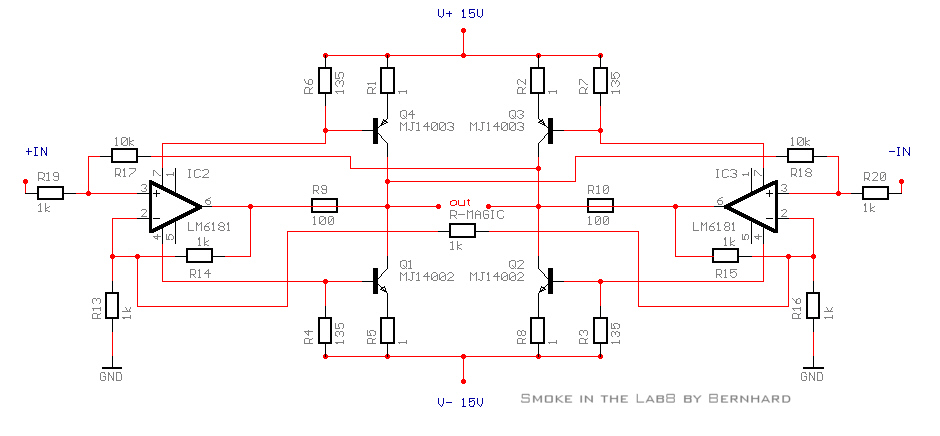
But...a warning to you builders. There was "smoke in the lab"!
Be careful when trimming R5/6/7/8.
I just blow my opamps! In the previous design, I could trim plenty with the base resistors without harm to components.
This is not the case with this circuit!
The "Magic" resistor is also a dangerous 'toy'.
I was able to listen to the amp for 15' but now the fun is over till
Tuesday.
/Hugo - very happy anyway
Just to let you know it works!!!
And it goes loud!!!
I managed to make the circuit work rather decently.
But...a warning to you builders. There was "smoke in the lab"!
Be careful when trimming R5/6/7/8.
I just blow my opamps! In the previous design, I could trim plenty with the base resistors without harm to components.
This is not the case with this circuit!
The "Magic" resistor is also a dangerous 'toy'.
I was able to listen to the amp for 15' but now the fun is over till
Tuesday.
/Hugo - very happy anyway
Great! I knew we would get it working eventually...
By the way, it was not my intention that you use not use emitter resistors on the bipolar devices. I would ordinarily recommend some large fraction of an ohm, and of course R5-8 should be resistors + potentiometers.
Another point: there will probably not be enough drive from something like a 6181, and for real power you will have to consider darlingtons or Mosfets.
Also: R9-12 values can be lowered to get more drive from a 6181, and this will get you more drive also.
Netlist said:
works!!!
blow my opamps!
Good news and at the same time unpleasant news.
According to the note about CFB amp, the +input node voltage forces the -input node voltage to follow and at the same time provide a low impedance path for the error current to flow. The "magic resistor" is assumed as having its role to resist the force and control the impedance. I would like to start with a rather higher value--e.g. 800ohms--of the magic resistor, reflecting that LM6181 has the absolute maximum invert input current rating of 15mA. And, I am still trying to figure out the roles of R10 and R12.
Waiting for LM6181...
JH
Nelson Pass said:
Mosfets.
I am going to test the amp with MJ transistors. Later, when I want it with Mosfets, is the changing of R5-8 all to be done (for Vgs and some idling current)?
JH
jh6you said:
"magic resistor"
I would like to maintain the following limit values.
JH
PS. Damit... Where are my ggg...girly-man chips?
Attachments

I dont want to be pert, but R9 R10 R11 R12 R13 R14 can be kicked out of the circuit.
In any case with the use of an ordinary OP.
In any case with the use of an ordinary OP.
Ok, I swapped the OPs to girly-man-chip, - still works. 🙂
Precautious made the connection of the wires of the magical-1k-resistor to the wires of the inverting inputs - also works, but with more gain. 🙂
But I need the 100ohm resistors on the OP output, if I short them, the PSU shuts down.
It seems, the LM got higher quiescent current as the NE5534 thus bias increases, my heatsinks are warmer...
Leaving out the 100ohm seems to further increase bias - which overloads my PSU.
With a more powerful PSU it should not be a problem. 🙂
Also due to my PSU Problem, bias current is only 0,35A, my 135ohm resistors should be 270ohm.
When playing with different values (on the sim, for the moment) for about all the resistors
that came out of Nelson's hat, it looks like he's got a very good hat. Apart from me playing with the base resistors and blowing the opamps. Of course I have emitter resistors (0.94 ohm) on the power transistors.
I also notice that a lower value for RO, around 10 - 50ohm is best,
but I could be wrong here of course.
Bernhard, watch the heat dissipation of the LM's!!!
/Hugo - will limit his power supplies next time 😉
Bernhard said:
not go for the 18V
Bernhard
I use +/- 15V supply, which are lower than the absolue maximum rated supply voltages of +/-18V. Please note that I have posted the sketch about the girly-man chips to remind of the maximum ratings.
By the way, your circuit looks very good!!!
JH
My girly-man-chips stay cold.
The resistors in the powersupply lines of the girly-man-chips (bias setting resistors) will limit power dissipation enough.
What I found while reading all the application notes is that
- too small feedback resistors or even shorts will cause oscillation.
- decoupling resistors of 47ohms ( in my circuit 100ohms provided by accident ) are recommended if the output capacitance exceeds some pFs, to prevent ringing.
- a cfb OP will function in a circuit like a vfb OP except input inpedance of the inverting input is very low.
Still waiting for enlightment why we need the cfb OP here. 😕

As the circuit functions with or without R0, we could implement a super-symmetry & gain-boost button + blue LED on the front panel of the amp
The resistors in the powersupply lines of the girly-man-chips (bias setting resistors) will limit power dissipation enough.
What I found while reading all the application notes is that
- too small feedback resistors or even shorts will cause oscillation.
- decoupling resistors of 47ohms ( in my circuit 100ohms provided by accident ) are recommended if the output capacitance exceeds some pFs, to prevent ringing.
- a cfb OP will function in a circuit like a vfb OP except input inpedance of the inverting input is very low.
Still waiting for enlightment why we need the cfb OP here. 😕
As the circuit functions with or without R0, we could implement a super-symmetry & gain-boost button + blue LED on the front panel of the amp
I think it’s not necessary to use CFB. Nelson only proposes it, mainly because it’s totally new, and CF has many advantages. (post #1). But you are on your way to prove that it can be done with VF also.Bernhard said:
Still waiting for enlightment why we need the cfb OP here. 😕
As the circuit functions with or without R0, we could implement a super-symmetry & gain-boost button + blue LED on the front panel of the amp
Yes, then we will have the ultimate "two in one amp".
BTW, my version is (was) driven balanced. I used Rod Elliott's
balanced line driver.
http://sound.westhost.com/project51.htm
/Hugo
Bernhard said:
R9 R10 R11 R12 R13 R14 can be kicked out.
As Nelson Pass said, R9-12 let us have output voltage swing higher than op amp output. I think they are optional resistors. If you want, you do not have to have them. Meanwhile, R13 and R14 are explained as for absolute DC stabilization.
As long as there are R15 and R16, I believe that I could make the magic resistor value lower. I had a plan to start with the magic resistor of 800 ohms. I however change my mind, and will begin with 100 ohms. Simultaneously, I will reduce R15 and R16 down to 1k, expecting an increased bandwidth. 🙂
JH
PS. The re-building is going well...
jh6you said:
PS. The re-building is going well...
Glad to hear that.
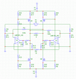
This could be a hesitating first attempt of a mosfet version.
R22/23 are only there to measure current in the sim.
/Hugo
Attachments
- Status
- Not open for further replies.
- Home
- Amplifiers
- Pass Labs
- Monolithic SuperSymmetry with Current Feedback