Op has mentioned "leveling speakers up" and by his nickname, it sure may very well be that his and my whereabouts are closely related if not the same, because I know something of such practice which started being offered to audiophiles some 25 years ago, or so.
There was this idea among people in the hifi business and second hand dealers that audiophiles being what they are, should be given a chance of upgrading their speakers and the decision was to offer 3 levels of upgrade. Those included exchanging internal speaker wires, caps and polarity of one of the drive units. In order for the audiophiles to believe in these sorts of mods, the local hifi periodical had reviewed some products that were modified in the described way, concluding changes to be perfectly alright and desirable. This kept going for some time but eventually stopped.
Really, the polarity changed? This would be done to any speaker?
Is that a 2.5 way still, 3rd order on the tweeter, 2nd on upper woofer with zobel to tweeter, and 2nd to lower woofer no zobel? What are the crossover points?
FYI, I measured the tweeter's Fs and it's ~800hz, give or take 20
What are the crossover points?
FYI, I measured the tweeter's Fs and it's ~800hz, give or take 20
What are the crossover points?
Last edited:
Hi again.
I moved to my new apartment in juli and I started to play with the speakers but its the same thing...problem with too much bass like in previous apartment
the room is 5mx4m
when I measured the speakers on connectors, both have 4ohms and they are 8ohms in specs on the web site
I tried to disconnect the bass unit and then I get 7ohms...the music sound nice and clean like it should but when the bass is connected I need to lower the bass pot on the amp to 9 clock to have the same clarity and soundstage....with the bass driver everything disappear there is only bass and highs..its like the bass driver destroys all until I lower it down
Well I like the sound without the bass driver and there is enough bass for me but still what is wrong with that speaker?
I did suggest earlier that you tried stuffing the reflex port with socks! 😀
I also suggested running a sim with similar drivers to see what is going on...
Seems like I have to do EVERYTHING round here! 🙄
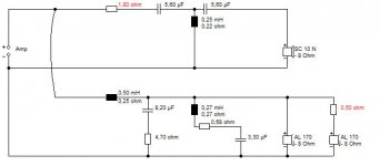
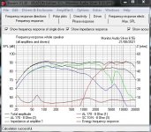
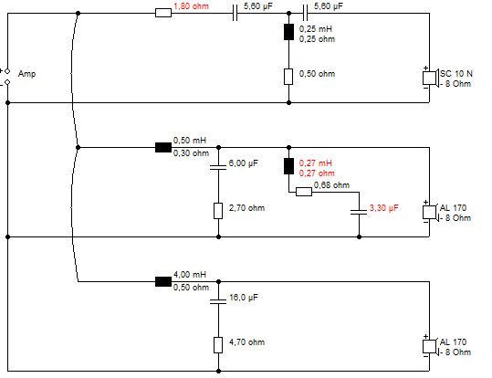
Here it is. Provided the midbasses are identical, we can convert the 2.5 way to TMM. No worse on impedance. In practice, it will work better than this, because my test metal AL170 drivers need a 6kHz notch, not 5kHz.
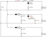
In 2.5 way form, there is a case to be made for notching the bass in the same way as the midbass. In TMM form, the notch should be 0.13mH/0.68R/6.6uF to get the right Q, but the original shouldn't be too bad. But not hard to unwind a coil. Notice I get positive polarity on the tweeter, unlike your PDF.
I make that a 4dB reduction in bass at one point. Might help.
I also suggested running a sim with similar drivers to see what is going on...
Seems like I have to do EVERYTHING round here! 🙄
Here it is. Provided the midbasses are identical, we can convert the 2.5 way to TMM. No worse on impedance. In practice, it will work better than this, because my test metal AL170 drivers need a 6kHz notch, not 5kHz.
In 2.5 way form, there is a case to be made for notching the bass in the same way as the midbass. In TMM form, the notch should be 0.13mH/0.68R/6.6uF to get the right Q, but the original shouldn't be too bad. But not hard to unwind a coil. Notice I get positive polarity on the tweeter, unlike your PDF.
I make that a 4dB reduction in bass at one point. Might help.
Attachments
Hi,
thanks for your effort...I found the issue....
the bass drivers on both speakers was connected wrong...polarity issue
now for the first time after 1.5 year of chasing whats wrong finally the stereo image is as it should be and I am enjoying the music 🙂
I was lucky that I didnt drive the speakers loud so nothing is damaged
I am the second owner so it might be that the first owner did some mistake
Ah, well done! Did you check for positive tweeter polarity, by the way? I found a discrepancy with the official circuit diagram... 😕
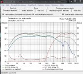
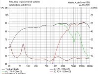
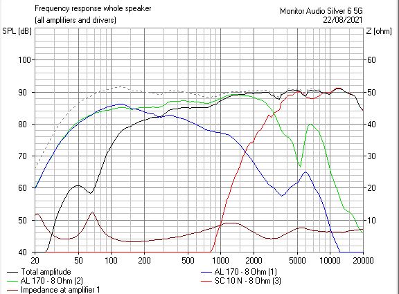
I ran a sim of your arrangement disconnecting the bass which you initially preferred. There is some risk in merely disconnecting a bass, it is better to disconnect before the crossover. Otherwise you get low impedance because the crossover becomes an undamped LCR shunt. The solid line versus the dotted impedance line. A commercial designer thinks about fault conditions leading to amp damage.
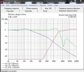
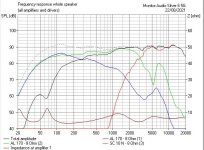
Bass in wrong polarity is dramatically wrong and lacking in bass. The second image. I would have heard that and the phasiness and diffuse imaging.
I ran a sim of your arrangement disconnecting the bass which you initially preferred. There is some risk in merely disconnecting a bass, it is better to disconnect before the crossover. Otherwise you get low impedance because the crossover becomes an undamped LCR shunt. The solid line versus the dotted impedance line. A commercial designer thinks about fault conditions leading to amp damage.
Bass in wrong polarity is dramatically wrong and lacking in bass. The second image. I would have heard that and the phasiness and diffuse imaging.
Attachments
Upgrade the capacitors with better ones from Mundorf, Miflex or Clarity caps and and resistors with Pathaudio resistors and you will get a better sound without changing the design.


Hans, I'm going to have to edit your post as it contains a 'base64' image do-dah that plays havoc with the forum 🙂
I did everything wrong 🙁
I turn the polarity on the bass driver as I wrote above and the sound is as I said much much better for me...but actualy I didnt check that well
I took the 1.5V battery to check the polarity on the driver to be sure what is plus and what is minus so thats done
And with the instrument I have measured 7.2V coming from the crossover to the driver and original it was right
When I turn the polarity I killed the bass and dont know why but it sounds good...thats why I was thinking yea case closed
But actualy the bass got wrong polarity...as you said System7 that its bad I cant connect that bass driver like that ...so I am still at the begining
I was measuring 4.7ohm on resistor which is on the bass driver so dont know if I should replace it with a bigger one
Also the bass driver is 9 ohm, and the mid i 7ohm
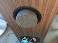
For the third time, put a sock in it! 😀
Or, for a more professional appearance, a foam bung.
Available from the popular internet sales outlets e.g. 2x Universal Foam Loud Speaker Port Bungs 75mm Dia x 40mm H - Removable Middles | eBay
Or, for a more professional appearance, a foam bung.
Available from the popular internet sales outlets e.g. 2x Universal Foam Loud Speaker Port Bungs 75mm Dia x 40mm H - Removable Middles | eBay
Attachments
Men, maybe I sound like a kid but thats the first thing that I tried....the bass is canceling the mids and port plug cant fix that
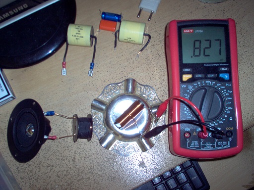
The business of fixing things starts with a visual inspection, and a bit of trial and error. Believe it or not. you can test a loudspeaker with a metal paperclip!
A 1.5V battery, a paperclip and a £5 multimeter is getting more serious...
In fact I have a much more competent £50 jobbie.
I had a look at your crossover and find little wrong with it. No need for snake-oil resistors or exotic capacitors here. Ferrite coils are OK too, unless you want to spend big bucks on aircoils. In fact ferrites are the only crossover components that are measureably worse than aircoils. The rest is snake-oil! 😀
https://www.diyaudio.com/forums/multi-way/370630-monitor-audio-silver-6-g5.html#post6608274
I won't paste the image because it is nearly 900kB jpeg, and overly large... 🙄
But what we have here is a biwireable input and a fairly competent 2.5 way:
That old 1.5V battery and paperclip can tell us about the relative polarity on the basses. They both should move forward on application of the battery +ve to +ve on the speaker input.
The tweeter polarity needs more thought. I would separate the tweeter input at the biwireable terminals and run a wire from the -ve to the tweeter. Now use your multimeter between that wire and either of the two tweeter terminals.
The earthy side of the tweeter will measure near zero ohms. The live side will be near 3-6 ohms. You will be hoping the live side is the red or positive marks on the tweeter, if my modelling is right.
the polarity on the tweeter in the pdf file that I have is wrong....All drivers are connected right as they have been from the begining....
the thing is that as soon the bass driver is connected and not placed in to the box everything is still working fine...when I place him in the mids are dissapearing...so with my knowledge I think that the bass and the mid woofer are not in the same phase
the thing is that as soon the bass driver is connected and not placed in to the box everything is still working fine...when I place him in the mids are dissapearing...so with my knowledge I think that the bass and the mid woofer are not in the same phase
I apologise - it was actually the 4th time of asking! 🙂
Thanks for the answer. I hope Steve can get to the bottom of your problem.
Thanks for the answer. I hope Steve can get to the bottom of your problem.
It's up to darkob to sort it out! I have laid out the method. Shouldn't be hard to trace the wires and resistances.
If the two basses are in wrong polarity, it is the bass that suffers, not the midrange! A wrongly wired tweeter would impact the midrange. 😕
In my experience, basses are marked in red on +ve:
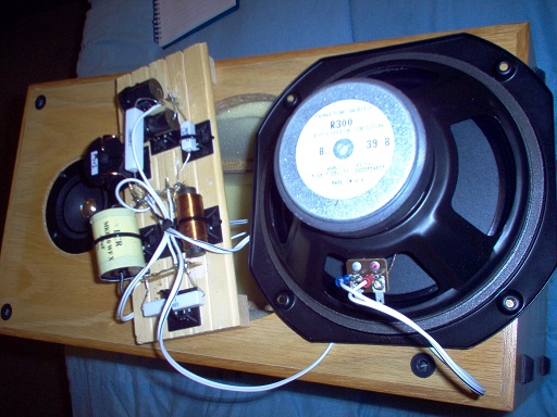
And you confirm that with a 1.5V battery. If putting the bass back in the box does strange things, try loosely fitting it back to front. Might sort it.
If the two basses are in wrong polarity, it is the bass that suffers, not the midrange! A wrongly wired tweeter would impact the midrange. 😕
In my experience, basses are marked in red on +ve:
And you confirm that with a 1.5V battery. If putting the bass back in the box does strange things, try loosely fitting it back to front. Might sort it.
Yes I agree with you system7....its up to me...I am goint to vacation so after that I am gonna jump into it 🙂
Monitor Audio used good components for the price points..however I had problems with the sound of mine!
Spending no more than £20 per component you can seriously upgrade the quality, i.e. have resistors with no inductance, inductors with no resistance, & capacitors with low ESR...also get rid of the big binding posts.
I would also recommend stripping out all the internal sound deadening, then using dilute PVA to key the inside & reinforce the corners with wooden blocks, & all the front & back panels to the sides with 12mmx12mm quadrant beading...then re-line the inside with Dynamat in the middle of the panels & then fit 35mm thick basic wadding (BAF ) ....
Makes a huge difference as the drivers are good
Here's my write up:-
https://www.diyaudio.com/community/...eakers-2010-2015yr-model.388989/#post-7089432
- Home
- Loudspeakers
- Multi-Way
- Monitor Audio Silver 6 G5