I usually insert a series resistance and measure the current through it by measuring the voltage across it. Works pretty well. I've done that with my HP3562A a number of times, but have yet to use the AP for the task. Impedance measurements haven't been the top priority lately.
Tom
Tom
Well... It's not every day that I get the chance to perform a competitive analysis, so when Anand offered to ship his amp, I took him up on it. I have never heard (or measured) a high-end class D amp and I was curious. It'll be interesting to play with and an interesting data point to have.
Tom
Tact Millennium was among the early entries. The system I listened to was actually very good. No coloration, detailed, but really high priced.
The New Class D which also started out in this forum measured quite well as far as I recall.
Having capability to maintain digital throughout the system provides significant benefits.
Last edited:
AndrewT,
The drawing to which I was referring used a two conductor cable, with shield.
The shield was connected at the RCA jack to signal-. Signal+ is the center pin of the RCA.
I am very impressed with the sound of the unit. Very clear.
The drawing to which I was referring used a two conductor cable, with shield.
The shield was connected at the RCA jack to signal-. Signal+ is the center pin of the RCA.
I am very impressed with the sound of the unit. Very clear.
BigE,
are you using a 2core+screen, or a 1core+screen, to connect the signal circuit?
In the 2core+screen, the signal Flow and Return use the 2 cores, the screen is connected to Chassis. If the screen is to be effective at vhf then both ends should be connected to Chassis.
In the 1core+screen the core is Signal Flow and the screen is Signal Return. The screen is part of the signal circuit, so does NOT get connected to Chassis.
Last edited:
It is a two core plus screen.
Tom's drawings show Signal+ on the PCB connected to the center pin of the RCA.
The screen is connected to the second core (Signal- at the PCB) at the RCA. It is not connected to the chassis here.
The PCB side is connected as normal one core to Signal-, one core to Signal+ and Screen to Screen.
The PCB side of the screen is connected to the chassis via the zero volt line to the safety earth lug. The zero volt line is directly connected to the safety earth.
No ground loop breaker is installed.
If I understand you, the Signal+ and Signal- should be connected to the cores, while the shield is connected to the chassis at both ends, one end at the RCA the other at safety earth. The PCB side should be independent of the zero volt line.
The screen of the incoming interconnect should be connnected to Chassis at the incoming "hole" through the chassis wall. Try not to use "pigtails", even short ones increase the impedance of the screen to chassis connection and that reduces the effectiveness of the filter. H.Ott goes even further and suggests there is improvement to be had in connecting the screen outside the chassis rather than bringing it through the "hole" in the wall and looping it back to the chassis as a circular screen (not a pigtail).
Yes, the screen should ideally be a perfect 'conduit', directly connecting equipment chassis to equipment chassis with zero parasitic inductance due to pigtail connections.The screen of the incoming interconnect should be connnected to Chassis at the incoming "hole" through the chassis wall. Try not to use "pigtails", even short ones increase the impedance of the screen to chassis connection and that reduces the effectiveness of the filter. H.Ott goes even further and suggests there is improvement to be had in connecting the screen outside the chassis rather than bringing it through the "hole" in the wall and looping it back to the chassis as a circular screen (not a pigtail).
XLR pin 1 to chassis connection should use flat strip conductor instead of typical wire, and as short as is possible.
Dan.
There are many things that work well in textbooks. There are also many things one can choose to geek out about. I suggest connecting the input cable as shown in the design documentation as this minimizes the ground impedance.
Ground loop breakers should not be necessary in a well-designed audio system. They are also against the electrical code in most countries.
Tom
Ground loop breakers should not be necessary in a well-designed audio system. They are also against the electrical code in most countries.
Tom
I was just pondering on this issue. Seem like the chassis coating would need to be smoothly milled out for best contact.The screen of the incoming interconnect should be connnected to Chassis at the incoming "hole" through the chassis wall. Try not to use "pigtails", even short ones increase the impedance of the screen to chassis connection and that reduces the effectiveness of the filter. H.Ott goes even further and suggests there is improvement to be had in connecting the screen outside the chassis rather than bringing it through the "hole" in the wall and looping it back to the chassis as a circular screen (not a pigtail).
I am curious, you have actual measurements to show the difference or is it experience from other projects?There are many things that work well in textbooks. There are also many things one can choose to geek out about. I suggest connecting the input cable as shown in the design documentation as this minimizes the ground impedance.
Ground loop breakers should not be necessary in a well-designed audio system. They are also against the electrical code in most countries.
Tom
I have tried ground loop breakers between equipment. They do solve some problems, but not the best solution.
Ground loop breakers should not be necessary in a well-designed audio system. They are also against the electrical code in most countries.
Tom
I think that a well designed Ground Loop Breaker between power ground and input ground is a safer option than using a thin trace to connect the two grounds.
I have tried ground loop breakers between equipment. They do solve some problems, but not the best solution.
Ground loop breakers may dull the symptoms, but don't solve the underlying problem.
In a single-ended system, the ground connection is part of the signal path, hence, any error signal developed on the ground net is treated as signal. Most audio systems contain several ground loops. In cases with only one loop, through the mains cable, the ground loop breaker may work. In systems with multiple ground loops, such as systems with multiple interconnects and multiple mains cables, adding a ground loop breaker may actually make the problems worse. In systems with multiple loops, a reasonable approach is to minimize the ground impedance. The ground loop breaker increases the ground impedance, hence, increases the error voltage.
Then there are the safety issues with ground breakers... Most electric codes require all metal parts of a piece of equipment to be grounded. The ground loop breaker violates this right off the bat.
The pro solution is to take the ground loops out of the signal path entirely. That's what a differential input does.
In my listening experience (with the biases and issues that come with sighted "tests"), differential signaling sounds better. I performed this test using a Parasound P3, two Parasound A23 in a vertical bi-amp on a pair of Dali Suite 2.8 speakers. The source was a Cambridge Azur 640 CD player. Switching from single ended to differential signaling (pseudo-differential on the CD player as it didn't have differential out) made quite an improvement in the sound quality.
I honestly didn't expect it to make a difference. Yet I found a higher level of detail and deeper space between instruments when using differential signaling.
This is of course just one experience based on a completely unscientific test. Usual disclaimers apply.
I don't have data to explain the perceived difference in sound quality, but my best guess is that most residential audio systems operate at the perception threshold for IMD caused by the error voltages developed across the various ground loops. This leads to a background layer of fuzziness that's hard to define by ear, but once gone leads to a higher level of enjoyment of the music.
Tom
The benefits of differential inputs are also pretty constant impedance over the audio band, the interconnects match the input impedance better. Most consumer electronics are single ended, this make things complicated. Ground interaction becomes very annoying also when you have USB DACs. Currently I have to select the proper cable through listening, just changing a different USB DAC requires a different cable seems to tell me the issue is complicated.
Last edited:
I don't which arrangement you are describing, but this is NOT how the Disconnecting Network works.The ground loop breaker increases the ground impedance, hence, increases the error voltage.
Neither does the added resistance as described by D.Joffe.
If your method does that, then it is not correct. That would explain why you are against using it.
Last edited:
They are also against the electrical code in most countries.
Not if done correctly.Most electric codes require all metal parts of a piece of equipment to be grounded. The ground loop breaker violates this right off the bat.
The PE wire should be permanently and mechanically connected to the Chassis. This is normally done at the location where the mains enters the Chassis.
That complies with code, as you state (correctly) to be necessary.
All exposed conductive parts should not be a hazard. This is normally done via the Chassis.
Then we come to the controversial:
What do we do with any exposed conductive parts that are isolated from the Chassis?
You can connect ALL of them directly to the Chassis.
You are claiming that this is the ONLY way to comply with code.
Are you really suggesting that every RCA/Phono barrel be directly connected to Chassis?
Are you really suggesting that every Speaker Terminal, that has an exposed conductive part, be directly connected to Chassis?
Exposed metal on a mains powered device can't be high impedance with respect to ground. If an amplifier output terminal is (ground +- some swing), that's fine, and if a RCA barrel has a current path to ground through some minimum impedance, that's also fine. But if these things are completely isolated from ground, that's bad.Are you really suggesting that every RCA/Phono barrel be directly connected to Chassis?
Are you really suggesting that every Speaker Terminal, that has an exposed conductive part, be directly connected to Chassis?
With limitations of course, if a metal part has no electrical connection to anything (eg, a metal nameplate or metal screws in a wooden enclosure) then it's fine. And rules are a bit different for 2-wire, double insulated devices.
Doing things like cutting the ground pin off a 3 lead power plug can cause very bad things to happen - eg, the Y capacitors can then make the chassis effectively float at 60VAC. Touch the chassis at the voltage peak and the Y cap discharges into you, you'll feel that. Plug something into the amp at that moment and you can very well blow things up.
Doing things like cutting the ground pin off a 3 lead power plug can cause very bad things to happen - eg, the Y capacitors can then make the chassis effectively float at 60VAC. Touch the chassis at the voltage peak and the Y cap discharges into you, you'll feel that. Plug something into the amp at that moment and you can very well blow things up.
Which is why I recommend against ground breakers. They're an unsafe, crappy solution for an issue that is more effectively dealt with by other means.
Tom
I think you can find some literature, either on the AP site, or AES concerning measurement of Class D amps. It is advisable to filter some of the HF hash before it enters the analyzer.
For reference, these articles give a good overview of the challenges measuring Class D (and sigma-delta DACs):
Bruce Hofer, "Measuring Switch-mode Power Amplifiers". Audio Precision, 2003: http://www.ap.com/download/file/19
TI SLOA068, "Guidelines for Measuring Audio Power Amplifier Performance", 2001: http://www.ti.com/lit/an/sloa068/sloa068.pdf
Tom
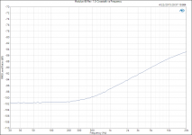
The long-awaited crosstalk measurement attached. I decided to use the prototype setup I've had running in my living room for the past couple of months for this measurement. I did absolutely nothing to tidy the layout. It's just two MOD86 R1.0 boards on a 0.4 K/W heat sink with a Power-86 off to the side.
The crosstalk measurement for MOD86 R2.0 and PAR86 R1.0 will need to wait until I get more channels built.
Nearly -102 dB crosstalk below 200 Hz. -97 dB @ 1 kHz, -85 dB @ 20 kHz. Pretty impressive if I may say so.
Tom
The crosstalk measurement for MOD86 R2.0 and PAR86 R1.0 will need to wait until I get more channels built.
Nearly -102 dB crosstalk below 200 Hz. -97 dB @ 1 kHz, -85 dB @ 20 kHz. Pretty impressive if I may say so.
Tom
Attachments
Last edited:
Which is why I recommend against ground breakers. They're an unsafe, crappy solution for an issue that is more effectively dealt with by other means.
The best ground breakers have 2 back to back zeners across the switch. This way, besides your usual hum, you can also have a rich mix of power line harmonics injected into your GND.
- Home
- Vendor's Bazaar
- Modulus-86: Composite amplifier achieving <0.0004 % THD+N.