The Mean Well RPS-400-27-C is tough to beat. You'll need two of them in series for ±27 V. The RPS-300-27-C would be a good option as well.
Do beware that some of the Mean Well RPS-series have been found to whine at light load. I have no experience with the RPS-300 series.
The RPS-200-27-C would be interesting as well. I'm pretty sure I've seen successful builds using those.
All of these are single supplies, so you'll need two in series. Mouser carries Mean Well.
Tom
Tom,
Are there any SMPS other than the Connex SMPS300REh that you would recommend?
Preferably something that can be sourced in NA. 🙂
The thought of paying $55.00 freight from China for a $72.00 item, or having to wait 3-4 months for the post system is not appealing... 🙁
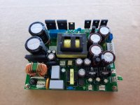
If you are not in a rush, I might be able to deliver your order on time, with express shipping to Canada (4 Days) @ 55$ for two units.
Attached is what you will get, Still missing the L-Shape heatsink
The only available voltage is +-35VDC.
* Stand by SMPS
* Standby switch
* DC Error input
Thanks!
Attachments
Last edited:
What is this supposed to mean?Buy one and you will find out.
If you are not in a rush, I might be able to deliver your order on time, with express shipping to Canada (4 Days) @ 55$ for two units.
Here's an idea: How about you start your own thread or website advertising these?
Another idea would be that you shipped me a free sample so I could test it with my amps. If I like it, I'll recommend it. Do note that I also take customer service into account when I make recommendations. "Buy one and find out" is not likely to get you high on my list of recommendations. Just saying...
I'm interested in supplies that can meet these requirements:
- Input voltage: 85-264 V AC, preferably without having to switch between 120/230 V operation. 48-62 Hz, min.
- Output voltage & current: I need three options:
- ±30 V @ 14 A peak (125 W average @ 10 dB CF)
- ±36 V @ 28 A peak (200 W average @ 10 dB CF)
- ±36 V @ 42 A peak (750 W average @ 10 dB CF).
- Protection: Over-temperature and preferably also over-current.
- Compliance: RoHS and CE.
You have my email address and PM.
Tom
Last edited:

Sure:
Connect RCA shell to XLR Pin 1.
Connect RCA centre to a switch that chooses between it and XLR Pin 2.
Connect RCA shell to a switch that chooses between it and XLR Pin 3.
Tom
Connect RCA shell to XLR Pin 1.
Connect RCA centre to a switch that chooses between it and XLR Pin 2.
Connect RCA shell to a switch that chooses between it and XLR Pin 3.
Tom
Is there any detriment if I only switch pin 3 and leave pin 2 connected at all times?
I will only use either Single or XLR at any time and never have both connected. This allows me to use a DPDT switch to choose XLR or single ended on a stereo amp.
Just about to start drilling my chassis. The above switch will immensely add to the versatility.
Thanks Tom
I will only use either Single or XLR at any time and never have both connected. This allows me to use a DPDT switch to choose XLR or single ended on a stereo amp.
Just about to start drilling my chassis. The above switch will immensely add to the versatility.
Thanks Tom
If you will never connect to both RCA and XLR at the same time, you can do this:
Connect RCA shell to XLR Pin 1
Connect RCA centre to XLR Pin 2
Add a switch, which connects XLR Pin 1 to XLR Pin 3 when the RCA input is used.
Some manufacturers use a wire staple jammed into the XLR connector for this. Cardas even sells an audiophile-approved wire staple. I much prefer to have a switch.
Tom
Thanks Tom, I will implement the switch as it will add a lot of versatility to the amplifier.
XLR - RCA label will be put on the switch !
XLR - RCA label will be put on the switch !
Hello,
I saw in an other post that I can add a volume pot at the output of the that1200 (pin 6).
Is 50k fine ? Where can I connect the ground ?
Thanks
I saw in an other post that I can add a volume pot at the output of the that1200 (pin 6).
Is 50k fine ? Where can I connect the ground ?
Thanks
My previous post should have gone into the Modulus-86 build thread - is there some way to move it there?
 Moved: but it looks like you already also posted it so now it is a dup. I'll delete one.
Hi, could someone confirm for me that the input impedance for the Modulus 86 is 48K in balanced mode?
I am trying to figure a few things for a possible PLXXO using 4 channels of Modulus 86.
Thanks,
Matt
I am trying to figure a few things for a possible PLXXO using 4 channels of Modulus 86.
Thanks,
Matt
Correct. It's 48 kΩ differential and 48 kΩ single-ended if you choose to drive it with a single-ended source. 48 kΩ it is.
Tom
Tom
Modulus-86 Rev. 3.0 is now shipping
The Modulus-86 Rev. 3.0 is now shipping. You can buy yours here: Modulus-86: DIY 65W power amplifier achieving – Neurochrome
You will also find a comprehensive set of measurements in the Performance Graphs tab of that page.
In addition to the excellent design documentation, I decided to create a build video. It's only my third video ever, so keep your expectations reasonable, please. 🙂 You can watch the build process here: How to Build a Neurochrome Modulus-86 High-End DIY Audio Amplifier - YouTube
Since its inception in 2014 the Modulus-86 has set the bar for low distortion DIY power amplifiers. The circuit has remained largely unchanged since the introduction of Rev. 2.0 in February of 2015.
Modulus-86 Rev. 3.0 represents a major design update. The input stage of the amp has been completely redesigned and now uses an LM4562 for even lower noise and distortion. The composite power amplifier section is now a differential amplifier and the DC servo has been eliminated. Modulus-86 Rev. 3.0 achieves state-of-the-art DC performance by other means.
The build cost is also lower. The parts necessary to populate the Modulus-86 Rev. 3.0 circuit board will set you back $50 per board or about 16% less than Rev. 2.4.
The new PCB layout uses four copper layers for better performance and improved routing. The board is the same size as previous versions (90 × 70 mm) and is now easier to mount in a chassis thanks to the added mounting brackets. All wiring now exit along the longer board edge, which makes it easier to mount multiple Modulus-86 on the same heat sink.
The boards are gold-plated, RoHS compatible, and made in Canada. All unpopulated Neurochrome PCBs are fully electrically tested by the manufacturer to ensure that they will work well in your hands.
Tom
Attachments
-
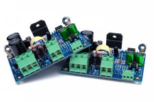 MOD86_R3p0_PairASSY.jpg226.8 KB · Views: 651
 -
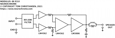 MOD86_R3p0_BlockDiagram.png23.7 KB · Views: 642
 -
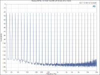
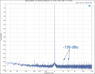 A_Modulus-86 Rev. 3.0_ Harmonic Spectrum (1 W, 8 ohm, 1 kHz, 0 dB = 1 W, 8 ohm).png51.5 KB · Views: 616
 -
 Modulus-86 Rev. 3.0_ Multi-Tone IMD (AP 32-tone, 40 W, 8 ohm).png55.8 KB · Views: 514
 -
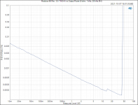 Modulus-86 Rev. 3.0_ THD+N vs Output Power (8 ohm, 1 kHz, 20 kHz BW).PNG53.2 KB · Views: 484
 -
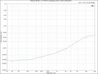 Modulus-86 Rev. 3.0_ THD+N vs Frequency (40 W, 8 ohm, 60 kHz BW).PNG38.5 KB · Views: 365
 -
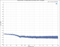 Modulus-86 Rev. 3.0_ Residual Mains Hum & Noise (1M FFT, 8 averages).png41.2 KB · Views: 413
- Home
- Vendor's Bazaar
- Modulus-86: Composite amplifier achieving <0.0004 % THD+N.