Thanks for the hints. I have done some simple stuff with ltspice in the past. I guess brushing up theses skills with your suggested excercise will be a good project for the next rainy weekend.
On another note. I read some stuff on the internet where it was questioned how reasonable it is to test amps mostly with sine waves on purely resistive loads. I remember that a while back you presented results of square wave input (with slopes equivalent to a 192kHz/24bit signals) in up to 1uF without ringing.
I however, have no idea if that is good or not as I have no clue what capacitive loading an amp sees when driving actual speakers. I googled but couldn't find a meaningful answer.
Could someone put some perspective to the above figures please? Would the Mod286 mono run into problems (e.g. ringing) at some point when driving my KEF R700 (see for impendence curve. KEF R700 loudspeaker Measurements | Stereophile.com )
Thanks a lot inadvance.
SH
On another note. I read some stuff on the internet where it was questioned how reasonable it is to test amps mostly with sine waves on purely resistive loads.
Sine waves and resistors are nice and well-defined. That's why they're used. You're absolutely in your right to challenge the external validity of such a test as reality offers much more complex signals and loads. You'll notice that Stereophile addresses one end of that by using their simulated speaker load, which is a reactive load. I address the other side of the equation by providing the results of a 32-tone IMD measurement as this replaces the sine wave with a test signal that's a lot closer to music than a sine wave. In fact, the 32-tone test signal sounds like an out-of-tune pipe organ and looks like a typical music signal on an oscilloscope.
I remember that a while back you presented results of square wave input (with slopes equivalent to a 192kHz/24bit signals) in up to 1uF without ringing.
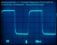
That tests the stability of the amp. If the amp can drive a heavily capacitive load without oscillation (which is not the same as ringing) it has a good stability margin. It's nearly impossible to avoid ringing - in particular in an amp with an output inductor. The ringing you see is often simply the resonance between the load capacitance and the output inductor, however, excessive ringing can also be a sign of instability. You can often tease the two apart by looking at the frequency of the ringing. If it's relatively constant, you're approaching instability. If it changes with the load capacitance, it's the result of an under-damped output inductor. You will be able to make any amplifier go unstable if you add enough capacitance on its output.
Would the Mod286 mono run into problems (e.g. ringing) at some point when driving my KEF R700
No.
Tom
I've seen AC lines measured with a Fluke Power Quality Meter graph to the 21st harmonic of 60 Hz.
Last edited:
I've seen AC lines measured with a Fluke Power Quality Meter graph to the 21st harmonic of 60 Hz.
That would certainly explain why the rectified waveform from your typical unregulated linear supply contains crap well into the low kHz range.
Tom
Sine waves and resistors are nice and well-defined. That's why they're used. You're absolutely in your right to challenge the external validity of such a test as reality offers much more complex signals and loads. You'll notice that Stereophile addresses one end of that by using their simulated speaker load, which is a reactive load. I address the other side of the equation by providing the results of a 32-tone IMD measurement as this replaces the sine wave with a test signal that's a lot closer to music than a sine wave. In fact, the 32-tone test signal sounds like an out-of-tune pipe organ and looks like a typical music signal on an oscilloscope.
That tests the stability of the amp. If the amp can drive a heavily capacitive load without oscillation (which is not the same as ringing) it has a good stability margin. It's nearly impossible to avoid ringing - in particular in an amp with an output inductor. The ringing you see is often simply the resonance between the load capacitance and the output inductor, however, excessive ringing can also be a sign of instability. You can often tease the two apart by looking at the frequency of the ringing. If it's relatively constant, you're approaching instability. If it changes with the load capacitance, it's the result of an under-damped output inductor. You will be able to make any amplifier go unstable if you add enough capacitance on its output.
No.
Tom
Ok got it. Thanks.
1) One more. Is the Mod286 / 86 ability to drive a 1uF load without ringing considered ok, good or great?
I just don't have a comparison with other amps and therefore no real reference for a judgement. For example the THD values of the Mod286 one can compare with reference values and I guess we all agree the Mods really shine in comparison to other power
2) You said my speakers wouldn't show any ringing when driven by the Mod286 under any conditions. How would I be able to tell by only looking at data for example for different speakers? (Please I don't want to challenge what you said, but just trying to learn)
Thx
SH
Last edited:
1) One more. Is the Mod286 / 86 ability to drive a 1uF load without ringing considered ok, good or great?
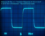
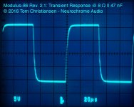
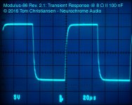
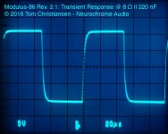
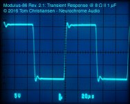
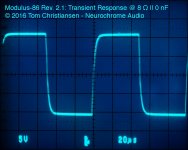
I've attached the transient response of the MOD86 driving 8 Ω || 0.01 - 1.0 uF. I'd say it's very well controlled.
I just don't have a comparison with other amps and therefore no real reference for a judgement.
Dig up an amplifier review from the 1980ies. It was a common test to run then. At least I seem to recall several magazines using it.
2) You said my speakers wouldn't show any ringing when driven by the Mod286 under any conditions. How would I be able to tell by only looking at data for example for different speakers?
I think you're trying to split hair here. Or maybe I'm over-interpreting. The amp will deliver a clean signal to the speaker. If the speaker is under-damped, it could still show ringing. That's determined by the speaker characteristics and not the amp characteristics. I'm not in control of the speaker characteristics.
"Any conditions"? Even if the amp is submerged in salt water? Where does "any conditions" end?
As far as I can figure, your speaker is a regular dynamic driver in a box. As such it tends to be pretty well-behaved as a load. I know the MOD86/286 well enough to know that it will perform flawlessly when presented with such a load. Therefore, I am confident that it will drive your speakers well.
Had your speakers been an electrostatic type, I'd examine the impedance curve more closely as those types of speakers tend to be rather capacitive. This shows as a decrease in speaker impedance vs frequency. Thankfully, while many electrostatic speakers are rather capacitive and present a low impedance through the audio band, the inductance of the step-up transformer prevents the capacitance from getting out of hand at frequencies beyond the audio band. Thus, this type of speakers aren't as challenging for amplifier stability as many would like to believe.
You can be confident that the MOD86/MOD286 will deliver a clean signal free of ringing to your speakers. What your speakers do with that is beyond my control but can be deduced from impulse response measurements and waterfall plots of your speakers. Looks like pretty nice speakers, by the way. I'm curious what goes on at 15-ish kHz in the waterfall plot, though.
Tom
Attachments
-
 MOD86_R2p1_Trans10V_8R10nF.jpg146 KB · Views: 1,164
 -
 MOD86_R2p1_Trans10V_8R47nF.jpg150 KB · Views: 1,164
 -
 MOD86_R2p1_Trans10V_8R100nF.jpg152.4 KB · Views: 1,147
 -
 MOD86_R2p1_Trans10V_8R220nF.jpg153.3 KB · Views: 1,140
 -
 MOD86_R2p1_Trans10V_8R470nF.jpg153.2 KB · Views: 1,136
 -
 MOD86_R2p1_Trans10V_8R1uF.jpg151.4 KB · Views: 186
 -
 MOD86_R2p1_Trans10V_8R0nF.jpg145.8 KB · Views: 198
Last edited:
Hello.
You made great job and gave a lot of usefull information considering designing layout for lm3886. Thank you!
Can you explain why you are not using Oscon in C1 and C16 now?
In this thread you recommended using 4.7uF + 22uf Oscon + 1000uF as supply decoupling capacitors.
LM3886 PCB vs Point-to-Point (with data)
Is it just price/performance optimization of final product?
Last edited:
Mostly cost/benefit optimization. Also not that a little ESR somewhere in the decoupling network is also needed to keep the worst resonances under control. Some apply snubbers, but an equally valid approach is to use the ESR of a regular electrolytic cap. It's all part of the engineering tradeoff. 🙂
Tom
Tom
Hello i need some help regarding the inputs of modulus86.
I m using a tda1543 and u need to know how many dc volts can i put to the amp input.
Right now i have a 2.2 cap on signal but i want to remove it possible without destroying something.
I m using a tda1543 and u need to know how many dc volts can i put to the amp input.
Right now i have a 2.2 cap on signal but i want to remove it possible without destroying something.
The Modulus-86 is DC coupled. It is not wise to rely on the DC servo to compensate for more than the mV-level offsets common in audio gear.
I don't remember the exact limit, but I seem to recall that the DC servo will be able to compensate for about 1 V of DC offset on the input.
I strongly advise you to ensure that you have 0 V DC at the input of the Modulus-86 (or any audio component for that matter).
Tom
I don't remember the exact limit, but I seem to recall that the DC servo will be able to compensate for about 1 V of DC offset on the input.
I strongly advise you to ensure that you have 0 V DC at the input of the Modulus-86 (or any audio component for that matter).
Tom
Does anybody know the absolut min. impedance for the Mod86? For the Mod686 I found that there it is 2Ohm. My horns have a minimum of 2,6Ohm from 150Hz to about 350Hz.
Wish you all a marry Christmas.
Wish you all a marry Christmas.
Probably the sensitivity will also enter into the calculus - it’s the total current draw that’s usually most worrisome
The Modulus-86 is stable with a 2 Ω load, so no concerns regarding stability. However, with 7 A output current, you'll only get 14 V developed across 2 Ω, which will result in a lot of dissipated power in the LM3886, hence, risk of overheating if operated there continuously. As Chris points out, if your horn is efficient, that's no big deal as you'll never operate the amp there for any length of time. But with less efficient speakers, I'd seriously consider the Modulus-286 instead.
Tom
Tom
Thank you. That is nice.
The horns have about 110dB/1W so using 10W is really loud. The horns start at 110Hz and the subs are active.
The horns have about 110dB/1W so using 10W is really loud. The horns start at 110Hz and the subs are active.
Tom, what are the power ratings for the new 186 and 286 into 2ohm loads? I don’t see those in the spec summaries, and I guess since few of us are operating domestic speakers with that low an impedance minimus that they’ve not been important figures to test / publish. Something like full range Apogee ribbons might be a concern, but I’d imagine high sensitivity compression driven front loaded horns should be less so - particularly with active crossovers to narrow the amps’ operating bandwidth.
I would hesitate to put a power number for 2 Ω on any of my amps. Rather, I'd call them 2 Ω stable and leave it at that. Of the three designs, the Modulus-286 is the best suited for a low-impedance load.
The problem is that if you want the amp to work well with a 2 Ω load, you'll have to reduce the supply voltage to avoid overheating the LM3886. The Modulus-86 will run a 2 Ω load just fine if modified to run on ±15-18 V rails. That'll only give you 10-15 W into 8 Ω, however, which is not marketable.
If you want an amp that can drive a 2 Ω load well, I suggest the Modulus-286 operated from a ±30 V supply. You'll get 40+ W into 8 Ω, 70+ W into 4 Ω, and 100+ W into 2 Ω.
And, yes, I did by accident once drive a 1 Ω load to well over 100 W with the MOD686. The amp survived just fine, but got very hot before the power supply shut down. The fact that the amp can survive such treatment should not be seen as an indicator that I recommend treating it like that continuously.
Tom
I'd probably go with a 2x15 V (50 VA per channel) transformer to get ±18 V when driving 2 Ω to clipping. You'll want to use R20=R22=3.3 kΩ and R9 = 24 kΩ to make the Modulus-86 work at the lower rail voltage.
With ±18 V rails, you should get about 50 W into 2 Ω.
Tom
With ±18 V rails, you should get about 50 W into 2 Ω.
Tom
Last edited:
Effectivity? You mean efficiency? The theoretical maximum efficiency for a Class B output stage is about 78.5%. A Class AB output stage will be slightly less efficient than Class B, so maybe 75%? My "LM3886 Calculator" spreadsheet says 71%, but I haven't done much to the modelling of efficiency.
Tom
Tom
- Home
- Vendor's Bazaar
- Modulus-86: Composite amplifier achieving <0.0004 % THD+N.