No worries. Thanks for following up.
Cool idea mounting the boards upside down. That may require a bracket to be fabricated to hold the board, but thankfully aluminum bends pretty easily... 🙂
Tom
Cool idea mounting the boards upside down. That may require a bracket to be fabricated to hold the board, but thankfully aluminum bends pretty easily... 🙂
Tom
Upside down
I mounted one board upside down to neaten the wiring layout.
Tom has a photo of mine which he might share.
It is a very good amp
tim
I mounted one board upside down to neaten the wiring layout.
Tom has a photo of mine which he might share.
It is a very good amp
tim
Hello, Hidy,
I had not heard about the AK4495SEQ until I saw your post. I looked around the net and found differing opinions about the quality and sound of various boards, especially the assembled Chinese versions versus the DIYINHK kit. Since you seem happy with yours I'd be curious about where you got it and your particular implementation (especially since the wide world of DIY DACs is new to me).
I'm building Tom's PARALLEL-86 and will eventually pair 4 channels of it with the Linkwitx LXmini...so I'm looking for DAC boards I can use with something like the miniDSP nanoDIGI.
Thanks,
Ronald
I mounted one board upside down to neaten the wiring layout.
Tom has a photo of mine which he might share.
It is a very good amp
tim
I do recall getting a picture from you. Now where in my seemingly endless inbox it is now is another question... 🙂 Feel free to share your build pictures here or in the build thread: http://www.diyaudio.com/forums/chip-amps/267802-modulus-86-build-thread.html
Tom
Hello, Hidy,
I had not heard about the AK4495SEQ until I saw your post. ... I'd be curious about where you got it and your particular implementation...
Ronald
Hi Ronald, I am using the DIYinHK AK4495SEQ version:
768kHz/32Bit AK4495SEQ DAC, I2S/DSD input - DIYINHK
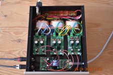
I am running it in hardware mode, using the differential output direct from the AK4495SEQ chip. I experimented different IV configurations and nothing compares to the transparency I get by cutting off the 2 traces leading to onboard IV stages and therefore bypassing the additional onboard IV stage altogether.
I am using the Short Delay Slow roll-off filter, it sounds best and measures well too.
The AK4495SEQ chip is ultra clean well in into the 200khz region and I think the Mod-86 has designed in good suppression/filtering for any noises beyond the 200khz region. So the AK4495SEQ and Mod-86 are a perfect matching pair that makes it possible to do away with any additional LPF in between the AK4495 chip and Mod-86, resulting in ultra transparency and cleanness. Tom, any comments on this?
I chose the Isolated XMOS, DAC and LED PCB purchase option, but I didn't implement the LED PCB because I don't need it and want simplicity with my build.
I have attached a photo of my AK4495SEQ DAC here for your reference.
Good luck with your build🙂
Attachments
Looks wonderful! I'll get to studying, and as time gets closer I may have to holler back.
Thank You!
BTW, folks...I'm a Yank who has been here in Germany since Spring 2014. I'm an early retiree who crossed the big pond to help care for elderly in-laws.
Thank You!
BTW, folks...I'm a Yank who has been here in Germany since Spring 2014. I'm an early retiree who crossed the big pond to help care for elderly in-laws.
BTW, folks...I'm a Yank who has been here in Germany since Spring 2014. I'm an early retiree who crossed the big pond to help care for elderly in-laws.
I know, I should not get into politics, but looking at the run-up to the US presidential elections, it might have been a wise move 🙂
(says the Finn married to an American, living in Holland)
Julf,
Funny. But, obviously enough of us must like it...cause we keep doing it.
Feel free to send me a private message sometimes.
Kirk Out
Funny. But, obviously enough of us must like it...cause we keep doing it.
Feel free to send me a private message sometimes.
Kirk Out
(says the Finn married to an American, living in Holland)
Damn I need to catch up, I'm only a brit, married to an Indian with an American daughter...
I suppose I might as well out myself as a Dane living in Canada after 16 years in the US. 🙂
It's an international world.
Tom
It's an international world.
Tom
Designed in Denmark, Made in Australia.I suppose I might as well out myself as a Dane living in Canada after 16 years in the US. 🙂
It's an international world.
Dan.
Tom - would you care to elaborate or give examples of how one might implement your That Driver or That Receiver products with existing equipment?
In my case for example, there are multiple SE sources (TT, CD, Tuner) a powered sub, SE pre & power amps... you get the picture. (my Mod-86 is the lonely differential box in the rack)
Where or how might one implement the That circuits in a legacy SE equipment chain? Is this evn their intended function or do I just build a That preamp to feed the M86 and call it good?
You'll get the best performance with differential signalling, so increasing the number of differential links is to your advantage.
In your situation, it would make the most sense to integrate a THAT Driver in your preamp and use its output to drive the MOD86.
If hacking into your existing preamp is not an attractive option, you can put the THAT Driver with a small power supply into a separate enclosure and attach it to your preamp with short RCA cables. Then you're free to run a differential link to the power amps.
Tom
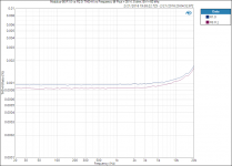
Occasionally builders will ask about the difference between Modulus-86 R1.0 and R2.0. I finally dug out a R1.0 module so I could take the measurement.
R2.0 provides 3-4 W higher output power and 10 dB lower residual mains hum. It also features an improved DC servo that settles in about 10 seconds (vs about a minute for the R1.0 servo). The THD is also a touch better for R2.0 as shown in attached graph.
Tom
R2.0 provides 3-4 W higher output power and 10 dB lower residual mains hum. It also features an improved DC servo that settles in about 10 seconds (vs about a minute for the R1.0 servo). The THD is also a touch better for R2.0 as shown in attached graph.
Tom
Attachments
Modulus-86 R2.1
As many of you are likely aware of, Texas Instruments decided to discontinue the 8-pin DIP version of the LME49710 used in the Modulus-86. Thankfully, they continue production of the TO-99 metal can version.
The Modulus-86 Rev. 2.1 addresses this and switches to the TO-99 version of the LME49710. In addition, Rev. 2.1 provides the following improvements on Rev. 2.0:
You can find the full specifications here: Neurochrome :: Modulus-86 Rev. 2.1.
A couple of highlights:
A couple of measurements are attached here. More are available on my website.
Tom
As many of you are likely aware of, Texas Instruments decided to discontinue the 8-pin DIP version of the LME49710 used in the Modulus-86. Thankfully, they continue production of the TO-99 metal can version.
The Modulus-86 Rev. 2.1 addresses this and switches to the TO-99 version of the LME49710. In addition, Rev. 2.1 provides the following improvements on Rev. 2.0:
- Slightly better THD near clipping.
- Uses current production readily available parts.
- Much improved chapters on power supply and heat sink dimensioning in the design documentation.
- Characterized performance at both 4 Ω and 8 Ω*load.
You can find the full specifications here: Neurochrome :: Modulus-86 Rev. 2.1.
A couple of highlights:
- 65 W into 4 Ω, 40 W into 8 Ω when using Power-86 with the recommended transformer.
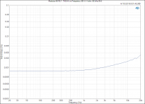
- Vanishingly low 0.000061 % THD (1 W, 8 Ω, 1 kHz).
- Ultra-low 0.000067 % THD (40 W, 8 Ω, 1 kHz).
- Ultra-low 0.00038 % THD+N (40 W, 8 Ω, 1 kHz).
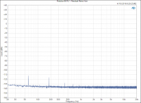
- Multi-tone IMD residual < -110 dBV (40 W, 8 Ω, AP 32-tone signal).
A couple of measurements are attached here. More are available on my website.
Tom
Attachments
-
 Modulus-86 R2.1_ Multi-Tone Test (40 W, 8 ohm).png68.8 KB · Views: 767
 -
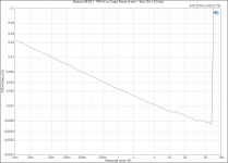
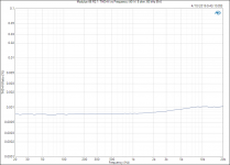 Modulus-86 R2.1_ THD+N vs Frequency (40 W, 8 ohm, 60 kHz BW).PNG25.7 KB · Views: 654
 -
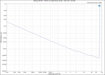
 Modulus-86 R2.1_ THD+N vs Frequency (65 W, 4 ohm, 60 kHz BW).PNG26.5 KB · Views: 643
 -
 Modulus-86 R2.1_ THD+N vs Output Power (8 ohm, 1 kHz, BW = 22 kHz).png37.6 KB · Views: 546
 -
 Modulus-86 R2.1_ THD+N vs Output Power (4 ohm, 1 kHz, BW = 22 kHz).PNG44.9 KB · Views: 155
 -
 Modulus-86 R2.1_ Residual Mains Hum.PNG46.8 KB · Views: 164
The multi-tone is pretty impressive.
Care to explain? I'm still learning, thank you!
Anand.
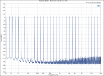
The multi-tone signal contains 32 tones, logarithmically spaced, from 16 Hz to 20 kHz. The total output power is 40 W into 8 Ω. All these tones will stir up some IMD. That's the grass you see growing between the tones once you get above 500 Hz - 1 kHz. even at 20 kHz, all IMD components are more than 110 dB below the fundamentals. Most of the IMD components are more than 115 dB below the fundamentals. That's the impressive part. Basically, this plot says that the amp doesn't generate appreciable IMD.
The components at 60, 180, and 300 Hz are supply related. Ignore those for the purpose of the multi-tone test.
Tom
The components at 60, 180, and 300 Hz are supply related. Ignore those for the purpose of the multi-tone test.
Tom
Tom beat me to it! Some people always complain that single tone or 19+20KHz don't tell you how an amplifier will work with music, which is wideband.
Now give or take a smidge because its early and I can't be arsed to convert. That graph is in dBV, so the peaks are around 3V each or 1W give or take.
The highest grot is -110dBV. If you are using 100dB/W horns in a REALLY good room with a 20dB noise floor, with nothing making noise (stop breathing please). your noise floor is 80 dB down on your fundamental.
Reality isn't that good as there is a voltage to power conversion going on so your -110dBV becomes only 55dB down in power terms, but its too early for me. Safe to say that, with your average 85dB speakers any hash is below the room noise floor in all cases.
- Home
- Vendor's Bazaar
- Modulus-86: Composite amplifier achieving <0.0004 % THD+N.