I've recently switched out a set of EL34 tubes in the attached circuit and find adjusting the bias a rather painful process as the adjustment is done on a net basis for both tubes and it is very hard to get the tubes matched to an acceptable level.
What would be the most efficient way to add in a second trimpot so each power tube could be adjusted separately?

What would be the most efficient way to add in a second trimpot so each power tube could be adjusted separately?

Your amplifier has Single Ended Output tubes.
Just matching the cathode current (plate current + screen current) does not insure that the gain of the tubes is the same.
After getting the cathode currents the same, you need to Either use very well matched output tubes (or at least check channel 1 and channel 2 input to output gains).
Unless your B+ power supply is fairly stiff, and you add a 2nd bias pot, you might find that when you adjust one tube's current, the other channel tube's current varies slightly. That is because when current varies, B+ varies, so the other tube's current changes.
Your EL34 tubes are in Ultra Linear, so any change of B+ will affect both the plate voltage, and even more importantly the screen voltage.
The plate impedance, rp is very high, so a B+ voltage change results in very little plate current change (like in Pentode mode).
But, the plate current is very sensitive to Screen voltage changes, so a B+ voltage changes does affect the plate current after all.
Of course, the other solution costs extra. Purchase a Very Well Matched pair of EL34 tubes.
Plug in and Play.
I drive over to Eurotubes.com and pick up all the JJ tubes I need. They re-test the tubes, and do Excellent tube current matching, gain, check for grid current, noise, etc.
I am curious about the use of an RF Choke for the screen, all chokes are [self] resonant.
I would much rather see a 100 Ohm or 200 Ohm resistor there.
Push Pull amplifiers need to have very well matched output tubes, it is paramount.
But that is a completely different story, and a different Thread.
Keep us posted as you modify this amplifier.
Happy modifying, and happy listening!
Fuling's suggestion is good, in addition I would place a 2.2 meg resistor from each pot wiper to the 47k end of the pot. The reason for this is if the pot goes noisy or the wiper goes open the will be a negative bias on the output tubes. Zero bias could damage the tubes and/or the output transformer.
Fixed Bias on SE amplifiers is not a good choice at all,
Cathode Biasing will solve 95% of your problems.
Where did this circuit come from, it is a loser, 👎
Cathode Biasing will solve 95% of your problems.
Where did this circuit come from, it is a loser, 👎
Individual Self Bias Resistors with individual bypass caps, makes it much easier.
And with 675V B+, those EL34 tubes will not miss the reduction of Plate to Cathode voltage because of the self bias voltage.
I wished I noticed the High Voltage B+ earlier.
A lot of parts can come out when the fixed bias circuit goes away, and all that is replaced by 1 resistor and 1 capacitor per EL34; self bias resistor and cap replaces the 10 Ohm cathode resistor.
If the tubes are reasonably matched, it is Plug and Play. No more bias adjustments!
The 100k g1 resistor connects to ground.
All the bias voltage circuit parts comes out.
The more I look at that circuit, the more I agree with jhstewart9.
The B+ secondary is 575V, that gives up to 805V B+.
That needs to be checked out.
The maximum screen voltage of an EL34 is 450V, Ouch!
"You should make things as simple as possible, but no simpler" - Albert Einstein
If the tube characteristics are badly matched, the channel to channel performance will not be equal.
Getting tubes from overseas is expensive. But some local vendors do a good job of matching for just a little more $$$.
And, there are those Vendors, local or remote, that do a very poor job of matching.
caveat emptor
Have fun modifying the amplifier to use Self Bias.
Then have fun listening!
Last edited:
Thanks for the interesting commentary here.
I've tested maybe half a dozen "matched" tubes varying from JJ, EH and PSVANE and very few of them even come close to having a near match on the bias. So it can turn into an expensive exercise!
It's possibly one of the most unique circuits I've come across. In fact I had it built for me by the transformer manufacturer Electra-Print (no longer in business as the owner has retired). I enjoy building amps but haven't tried anything with a B+ at these levels!!
Here are the comments from the designer, in more detail - sorry for the length but it is worth reading:
"High Perveance, Enhanced Class A3 tube operation.
To start off with, the 300B and other favorite audio triodes, being the tubes of choice over these many years, are possibly on their way to retirement.
Example, the 300B class A operation, 400v plate to filament, at 100ma is 40 watts, full plate dissipation, this offers a 20-25% output power of 8-10 watts, into a 3K primary.
The maximum power is at slight symmetrical clipping.
At that point, you always see a rise in plate current. This rise is calmly accepted and never pursued due to “ just more distortion there” plate will get red at this point anyway.
Class A3 operation, partially discovered in 2010
Using the 300B example and subject of experimentation.
A3 became a practical addition to power triode tube operation using fairly inexpensive triodes, such as the Sovtek 6A3 as a 300B so no damage to the real ones due to their high value.
Operating this tube at a higher plate voltage, lower plate current, lower plate dissipation, and higher load impedance. 500v @ 70ma plate or 35 watt plate dissipation (no red plate) gave an output of 14-15 watts to slight clipping with very acceptable distortion measurements.
This shows a 40% efficiency in this new class of operation.
Also the drive needed was much less that the standard Class A used.
Existing tube operating classifications
From the Radio Amateurs handbook, 1967 (middle of the tube era)
Class A is a tube that is biased so output wave shape is identical to input wave shape and amplified.
Class A1 is a tube biased more negative so a larger signal can be handled.
Class A2 is a biased tube grid using power, and having grid current flow in the least part of the cycle and power amplification ratio is not infinite, it is necessary to use a power amplifier to drive this tube.
Class AB and AB1, used in push/pull only and its variation of bias setting between class A and B operation, output transformer application/s and distortion conditions, under controlled and selected NFB.
Class B always used in push/pull and biased at tubes cut off so each tube conducts on each half with the use of a phase splitting driver circuit. Very high Power results but in this operation, it has output transformer crossover distortion and NFB is needed to clean this up.
Class C operation is primarily used to RF use due to it being bias higher, so tube conduction starts at higher up on the 180 degree half cycle (maybe at 30 degrees) of B operation, having very high plate voltage/s and allowing very high power generation but extremely distorted and never used in audio power.
Note that the “A3” has never been used so we decided to use this “A3” for our new operational means, due to it being a relatively close to Class A operation only.
Enhancing A3
With the 300B ( Sovtek 6A3) test subject used, increasing the plate voltage to 700v at 60ma, a 42 watt plate, a slightly higher plate dissipation and a slight red plate.
With a different plate loading this gave 20-22 watts of very clean power, this resulted in a power efficiency of 52% and in many tests work fine, built many amps with this operation with no failures to date.
Do not use real 300B’s or those expensive boutique tubes, doing this, they may not survive the differences, flashover from gas in the old stock 300B’s! All we know is the test subject, the Sovtek 6A3 works fine.
Introducing High Perveance-Enhanced A3
Having found the limits of the basic popular SE power triode and some others such as the miniature 5687 with an output of 7 clean watts from one tube (paralleled both sections) at a total of 24ma with 525v on the plates and slight red plates.
We knew of the red plate/s having a hard time being accepted within the audiophile crowd. Actually slightly red plates do not compromise the tube at all, Eimac, the transmitting tube company since the 1940’s have been using full red plate power tubes with forced air cooling to date, delivering 1000’s of watts of power!!!
So, looking into other tubes such as “high Perveance tubes” (large cathodes) power pentodes, we found an interesting set of rules.
The addition of the cap on top of these tubes is the reason they can be used with high plate voltages without arcing. The 807 tube is just a 6L6 with a plate cap and a rating of 750v plus signal, capable!!!
Experiments with these tubes showed real promise and very interesting features.
We did the usual experiments and found we could get near 100% power output of the tubes rated plate dissipation “without” the red plate!!!!
An 18 watt plate pentode gave a very good delivery of 17 watts output, no red plate.
The screen added to this efficiency. Using a tap of various percentages gave us a look into the heart of these tubes and showed the need for various ratios of tap percentages, like the UL tap on p-p outputs. This tap also adjusts the distortion figure due to no NFB (negative feedback) is used in this circuit.
This tap is in phase with the plate so it speeds up the electron flow, thus more power.
Paralleling these tubes gave the same results as the standard operation and half the load impedance. Up to 38 watts resulted in one test of two tubes in parallel.
The one feature that caught our eye was, the very low idle current used, resulting in an output transformer 25% of the usual core mass needed to the same power and full bandwidth as in a standard SE class A operation!!!! this is really good!!!
Theory of High Perveance power pentodes characteristics.
Having a full library of all things vacuum tubes back to the 1920’s and building my own tube transmitters in the 1950’s, to date, this new operation of power pentodes is not in those books at all!! not even a hint.
We then looked else wear only to find these interesting actions in books on Particle Physics and the help from a very good friend in the particle physics field, Dr. Rob Ashlock.
The theory holds fairly true of these characteristics we saw.
First, Electrons accelerated at higher speeds with higher voltage/s, (Ev) will produce more power colliding with its positive destination (the plate).
Second, Electron clouds forming around the emitter (Cathode) are drawn through a control grid at a given speed to its positive element based on the vacuum and voltage potential, this lowers the drive voltage needed for the same power output, it becomes more sensitive!
Third, the screen acts as an electron gun accelerator as in a picture tube and in phase, signal wise, offers the effect of velocity modulation increasing power gain on signal peaks based on the doubling of electron voltage (Ev) increases the power by a factor of four.
Thus, the high plate voltage, high screen voltage accelerator and lower electron cloud density, (lower cathode current) and amplitude of signal being velocity modulated instead of just a constant current signal adding and subtracting, as in standard class A.
This offers a 70-80% increase of power output efficiency over the old Class A Triodes.
Also, in this operation, the drive voltage or grid admittance needed is a fraction of what was commonly used. A3 operation allows the grid to be “more” sensitive so less drive current needed.
We now drive an EL34 to 21 watts with one section of a 12AX7 running less than 1ma through it with 550v on its plate. This tube must be selected and R values tuned for least IMD. Built many amps with this combination these few years.
Example compared to standard 300B in class A
300B, 400v at 100ma = 40 watt plate dissipation!! Standard operation.
The 300B in this standard class A operation will offer an output of about 10 watts, about 20-25% of the full plate dissipation, so what does the other 30 watts of power do??, “nothing at all”, just runs up the electric bill and demands a 3-5K load and a very large output transformer for the 100ma core stack to soak up!!!
The electron flow of 40 watts of power is being modulated by its grid only as a subtraction from the full 40 watt electron flow to offer the 20-25% modulation of the plate and output trans for that 10 watts output!!
That is about all there is to it!!!
The enhanced A3 does not do this.
High Perveance tube, 6LQ6, 850v at 40ma = 34 watt plate dissipation, approximately 28 watts maximum output, about 83% of plate dissipation, and less than 50% of transformer core mass of 100ma output transformer, needed.
A 4D32 was tried in A3 SE and got 38 watts in this operation but plate voltage was very high, but do-able to the brave at heart!!!
Results of listening tests.
First tested was the 5687 (each tube, paralleled sections), first thing heard was imaging that had “pin point” placement, unlike imaging that is just there, blending in and out with each instrument. The sound of each instrument was, “fast” !, a popular audiophile description but, described it accurately !
The test speakers are open baffle neodymium arrays, a Bruce Edgar involved, late design, with a 97-98 db SPL. No resistive loss devices used in crossovers, just reactive.
Second test was double the power using “High Perveance tubes and enhanced A3”, the same “pin point” imaging, still fast and, an instrument could get very loud in its placement without moving!! A very different delivery was heard.
We recently had this circuit used with EdgarHorns and other horn systems, in the over 100db range. The imaging was “holographic” or 3D. why? We have no idea, yet.
To look back on the past amplifiers we tested, some with much higher power, SE class A and Push Pull designs, they did not “pin point” the images and each instrument was just there and so on, clean and accurate, state of the art, we can call it.
We believe the difference from the old tests is having the high “power gain” and smaller output transformer offering a higher power, full bandwidth and using much less core mass so core mag and re-mag is now a fraction of a problem.
Types of power output configurations.
As for push pull, and its algebraically nulling out small applied amounts of signal arriving exactly the same time on each primary half, has a real problem doing imaging well, resulting in 5-10% of the original signal removed or nulled out, imaging is a product of the recorded instruments waveform/s being totally heard and recorded. If certain minute waveforms are not present, it will not appear properly within the air between the speakers reproducing it. An ongoing theory.
As for negative feedback, this is actually a “non-linear compression” and alters the music delivery in ways not to many can measure but cleans up the distortion and adds another type, so why bother. Using a good dual trace scope, you can see this.
One thing to think about is, a dominate or loud instrument in the music will offer the imposed negative gain (NFB) used reduce “all” the other instruments levels also so an incorrect reproduction is now present !!
As for solid state, the flaw is, the output power/levels will change in operation from varying load impedance of the moving speaker/s. example SS published specs, “100watts to 8 ohms, 200 watts to 4 ohms”. Measures very clean with one test tone!! They all do.
So identical signal in and signal out, is fairly impossible as is also the mentioned above!
Thus, SE power, done well , should and will display the most truest, best imaging and instrument authority that is possible for a given recording.
New descriptive specifications.
The ongoing experiments of Enhanced A3 so far has shown another set of rules needed to show the decades of accepted audio specifications have been incorrect and detrimental in the real display of acoustical power! Examples below,
The commonly used -1db 20hz to 20Khz at some nominal point of power will offer much more of a problem than the old Western Electric specs of -1db 50hz to 10khz used in movies and pro-audio etc, during that era.
Capitalizing on audio equipment exaggerating the spec numbers as horse power did to car sales. The specs wars then went on to the present, the 100’s of computerized and useless published but impressive newly worded advertisement effectively, lies, supporting audio equipment, is just more predatory capitalism and corruption.
I know of no one that can even explain/duplicate or understand, the new published specs in these magazines to date.
A3 operation has led to a few discoveries with the common and largely accepted specs!!
First one was “the upper range needed to hear the harmonics of the instruments”. Not true! The timbre of each instrument, the “sound heard” is the product of that instrument recorded. These harmonics are not up there !!, they are already on the instrument sound.
There are no harmonics higher than the highest note played from the whole orchestra!!
The highest note is from the piccolo, this is the C, four octaves above middle C, little over 6Khz, that is it, nothing above 6khz that is needed by the amplifier to reproduce!!.
Above 10khz the amp has really nothing to do but may produce things not heard on the recording maybe tube residual noise, oscillations, or signals developed by the amplifier circuit ? This could generate IMD products mixing with the “lower heard” music.
So limiting the highs on the amplifier will clear up the “highs heard”.
Pipe organ music does have its place in the spectrum considering what it does that other music will not offer.
As for the bass end, this one is very hard to imagine its effect due to it being a very large waveform that will carry into the air, most of the other instruments in the recording. The placement of the bass source is very hard to convey in a recording and a reproduction sound room.
Therefor the bass, a double Bass cello, lowest note is around 40hz is heard, nothing near 20hz is every heard unless you consider the people that like lots of sub bass that offers brain beta damage and Pneumothorax (collapsing lung)!!!
Position of bass source in the recording is hard to deal with but, point is, the higher the bass response the less problematic sound systems are.
Acoustical intermodulation problems are predominantly all bass generated (mixing with mids and highs).
Therefore, limiting the spectrum and acoustical mass of the real music will show a very real and accurate delivery into a common listening room. it’s up to the person doing the recording and the position of the bass source.
A spectrum of -1db 40 to 10khz is all that is really needed for best reproduced, least interacting and interfering amongst the musical Instruments within the amplifier workings.
Every movie made from the 1930’s to about the late 80’s is proof that -1db20-20khz is not needed. All the sounds in the movie are reproduced perfectly, considering.
(except, Sprach Zarathustra) (2001 fanfare).
We have found that the IMD measurements we use intensively are subject to problems of having a wider bandwidth !! having it somewhat limited allowed a much cleaner delivery and extremely accurate, pinpoint imaging and full music response, as a result of corrupting the spectrum with circuitry wanting to responding to nothing.
Of course we will get a lot of flak on these latest statements but, I could be corrected if someone was to prove I am wrong."
lordearl,
I was editing and adding to my Post # 5, when you Posted # 6.
Important: Please go back and re-read my Post # 5 to see my added information.
Thanks.
A choke input supply can take a 575V secondary and give a more reasonable B+ of about 500V.
I have designed and built a single ended EL34 Ultra Linear amplifier, but that was quite a while ago.
For an EL34, a 1Volt change in bias causes about 11mA change in plate current (Gm = 11,000 uMhos). Sensitive!
Self bias can be your friend.
Have fun!
Last edited:
lordearl,
You caught me editing again, this time Post # 8.
I have to start a thread of my own tonight (I hope).
You caught me editing again, this time Post # 8.
I have to start a thread of my own tonight (I hope).
lordeael
I would personally go for Cathode Biasing. What is the impedance of the output transformer? What current do you bias the tubes too? Is the amplifiers performance acceptable as it is? I have always found the screen grids of EL34's rather fragile and tend to respect their published ratings.
Please excuse all my questions, I may do a loadline.
As 6A3 said
Have Fun!
Thanks @Fuling @Tubekwk @6A3sUMMER @jhstewart9
I really appreciate the input here as working on a circuit like this is new territory.
The amp itself performs nicely, mind you I am only comparing it to a 6V6 push pull and a JLH 1969 solid state amp - which are completely different topologies.
Sorry - the impedance of the output transformer I assume you mean at the speaker terminal, it's 8 Ohms. Any other details I'd need to check with the manufacturer.
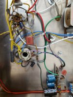
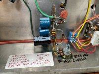
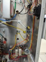
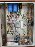
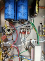
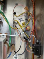
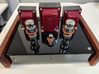
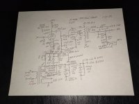
I've attached some photos of the internals of the amplifier along with the schematic again so it's all in one location.
Plenty of space in the chassis to do some suitable modifications.
The bias should measure between 37mV and 40mV but I can rarely (if ever) get two EL34s to be within this range. For example, at the moment the two Electro Harmonix valves in there are measuring 35mV and 40mV.
I really appreciate the input here as working on a circuit like this is new territory.
The amp itself performs nicely, mind you I am only comparing it to a 6V6 push pull and a JLH 1969 solid state amp - which are completely different topologies.
Sorry - the impedance of the output transformer I assume you mean at the speaker terminal, it's 8 Ohms. Any other details I'd need to check with the manufacturer.
I've attached some photos of the internals of the amplifier along with the schematic again so it's all in one location.
Plenty of space in the chassis to do some suitable modifications.
The bias should measure between 37mV and 40mV but I can rarely (if ever) get two EL34s to be within this range. For example, at the moment the two Electro Harmonix valves in there are measuring 35mV and 40mV.
Attachments
-
 IMG20230706095627.jpg525.8 KB · Views: 119
 -
 IMG20230706095650.jpg457.4 KB · Views: 97
 -
 IMG20230706095633.jpg457.8 KB · Views: 98
 -
 IMG20230706095517.jpg646.7 KB · Views: 97
 -
 IMG20230706095623.jpg511.5 KB · Views: 91
 -
 IMG20230706095615.jpg547.9 KB · Views: 94
 -
 IMG20230706094730.jpg360.4 KB · Views: 119
 -
 48935.jpg352.1 KB · Views: 118
An amazing collection of misunderstandings and half-truths, concluding with "Prove me wrong." I guess that's the current state of a lot of things in our post-truth "alternative facts" world.Of course we will get a lot of flak on these latest statements but, I could be corrected if someone was to prove I am wrong."
Chris
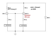
Cathode Bias, The Great Leveler
I put this simple demo together a while back to demonstrate how cathode bias stabilizes the tubes operating point.
In this case the tubes are 6V6s, one with normal emission, the other 25% low emission.
The cathode bias in this example gets the emission to only 9% difference.
For Cathode Bias all the Reactive Impedance's drop out of the calculation of steady state, Only the DC values are required.
Attachments
Running a nominal 625V B+ on the screen of EL34 with a max spec of 500V is somewhat adventurous.😱
What happens if the supply line goes high? This amp would probably not pass UL. 👎
What happens if the supply line goes high? This amp would probably not pass UL. 👎
lordearl,
37mV and a 10 Ohm cathode resistor = 3.7mA
40mV and a 10 Ohm cathode resistor = 4.0mA
Not working well
Perhaps your cathode resistors are 1 Ohm, then . . .
37mV and a 1 Ohm cathode resistor = 37mA
40mV and a 1 Ohm cathode resistor = 40mA
That is more like it.
Sorry just switched to auto range on the multi meter it looks accurate, here are the readings. Cathode resistor is definitely 10R.
Higher than rated voltage on a screen is one of my most unliked conditions for a vacuum tube.
Once, a US company I worked for had CSA officials over to look at some of our products, one product was custom designed and built by a contractor.
Sometimes, there is good engineering, but an oversight and a parts failure can do some damage.
The product was a lead acid gel cell in one enclosure, and a 110V inverter in another enclosure.
There was a wire and connector from the battery enclosure, to the inverter enclosure.
There was no fuse in the battery enclosure to its output.
Unfortunately, a small capacitor at the inverter input shorted.
The wire went up in smoke!
What an embarrassment to all.
The design was corrected (a proper fuse was added inside the battery enclosure).
Thanks for this @jhstewart9 and @6A3sUMMER, this is somewhat alarming.
I am rather concerned and so would like to modify the circuit to have safer operating conditions, and to be self biased.
What is the step by step process I will need to follow to make the necessary changes?
I am rather concerned and so would like to modify the circuit to have safer operating conditions, and to be self biased.
What is the step by step process I will need to follow to make the necessary changes?
Those voltages are 10 times larger than 37mV and 40mV.
Your meter readings show much more correct voltages of 354.5mV and 395.7mV.
35.45mA and 39.57mA.
Much better!
Change your B+ filter to a Choke Input Filter. You have way too much Screen Voltage. It will work until it blows up!
Prevent the "Surviving Spouse Syndrome".
Your meter readings show much more correct voltages of 354.5mV and 395.7mV.
35.45mA and 39.57mA.
Much better!
Change your B+ filter to a Choke Input Filter. You have way too much Screen Voltage. It will work until it blows up!
Prevent the "Surviving Spouse Syndrome".
lordearl
When I asked what is the impedance of the output transformer? I wanted to know the primary impedance of the transformer as this determines the operating conditions of the output tube. Going to cathode bias will help reduce the voltage across the tube (measure cathode to anode). With the transformer information we can plot a loadline and be of more help with the modifications. As 6A3 said a choke input will reduce the B+ voltage to a more acceptable level.
When I asked what is the impedance of the output transformer? I wanted to know the primary impedance of the transformer as this determines the operating conditions of the output tube. Going to cathode bias will help reduce the voltage across the tube (measure cathode to anode). With the transformer information we can plot a loadline and be of more help with the modifications. As 6A3 said a choke input will reduce the B+ voltage to a more acceptable level.
- Home
- Amplifiers
- Tubes / Valves
- modifying valve amp with net/single bias trimpot